Switched reluctance motor and its control method

A technology of switched reluctance motors and control methods, applied to synchronous generators, electromechanical devices, electrical components, etc., can solve the problems of unbalanced current in each phase, high technical requirements, high noise, etc., and achieve precise rotor angular position and rotational speed , Strong anti-interference ability, high resolution effect

Active Publication Date: 2020-09-18
丁金龙
View PDF5 Cites 0 Cited by
  • Summary
  • Abstract
  • Description
  • Claims
  • Application Information

AI Technical Summary

Problems solved by technology

[0003] However, when the photoelectric switch sensor is used as the sensor of angular velocity and rotor angular position, the resolution of the obtained angular position information is low and the speed response is slow. When rotating, due to the long signal transition cycle, the response is slow, which in turn affects the low-speed performance of the motor; and when the angular position sensor is installed on the motor, the operator needs to set the zero point, which will easily lead to large errors. This process also requires The operator has certain experience and has high technical requirements; in addition, the detection of the angular position of the rotor depends on the machining accuracy of the photoelectric sensor code disc. When the machining accuracy of the code disc is not high enough, it will affect the accuracy of speed calculation and motor angle control. It is easy to cause unbalanced current of each phase during motor control, motor vibration and noise, and the power device of the controller is easily damaged

Method used


Image

  • Switched reluctance motor and its control method
  • Switched reluctance motor and its control method
  • Switched reluctance motor and its control method

Examples


Embodiment 1

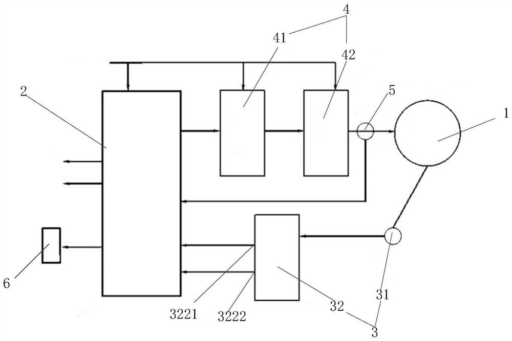
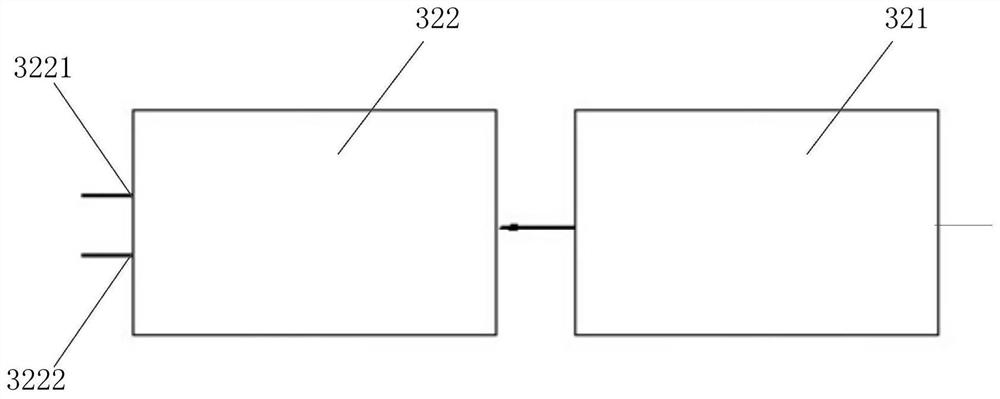
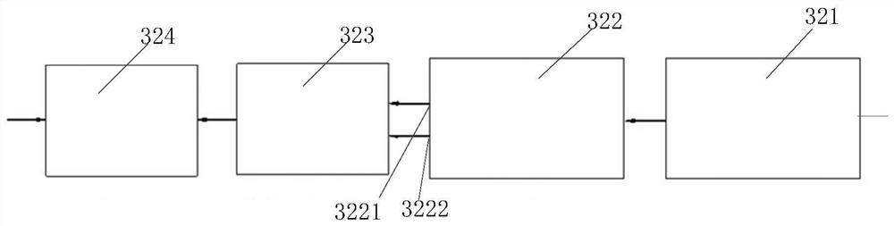
[0053] Such as figure 1 As shown, a switched reluctance motor proposed in Embodiment 1 of the present invention includes: a motor 1, a control module 2, an output module 4 and a detection module 3, the first end of the output module 4 is connected to the control module 2, and the output module The second end of 4 is connected to the motor 1 for outputting a control signal to the motor 1; the detection module 3 includes a rotary transformer 31 and a signal processing circuit 32, the rotary transformer 31 is arranged in the motor 1, and the signal processing circuit 32 is connected to the rotary transformer 31 and between the control module 2; wherein, the rotary transformer 31 is used to detect the angular position information and the rotating speed of the rotor of the motor 1 to obtain the angular position information signal and the rotating speed signal, and transmit the angular position information signal and the rotating speed signal to the signal processing circuit 32, The...

Embodiment 2

[0065] Such as Figure 4 As shown, a control method for a switched reluctance motor proposed in Embodiment 2 of the present invention includes:

[0066] Calibration status:

[0067] 101. The control module outputs a one-phase current control signal, so that the motor rotor is locked at the position where one phase is at the maximum inductance. The control module obtains the absolute angular position information of the motor rotor, calculates the rotor offset, and calculates the index value and Initialize the control module;

[0068] Specifically, since there is a certain offset between the detection starting point of the resolver and the rotor when the resolver is installed, it is necessary to set the zero point to eliminate errors caused during installation. Its specific operation can be described as follows: After the switched reluctance motor is powered on, a constant current value is passed to one phase of the motor so that it is located at the maximum inductance positio...


PUM


Abstract

The invention relates to a switched reluctance motor and a control method thereof, and relates to the technical field of motors. According to the main technical scheme, the switched reluctance motor comprises a motor, a control module, an output module and a detection module; the two ends of the output module are connected with the control module and the motor respectively, and the output module is used for outputting a control signal to the motor; the detection module comprises a rotary transformer and a signal processing circuit; the rotary transformer is arranged in the motor; the signal processing circuit is connected between the rotary transformer and the control module; the rotary transformer is used for detecting angular position information and a rotating speed of a rotor of the motor to obtain an angular position information signal and a rotating speed signal, and transmitting the angular position information signal and the rotating speed signal to the signal processing circuit; and the signal processing circuit is used for processing the angular position information signal and the rotating speed signal and then transmitting the processed angular position information signal and rotating speed signal to the control module. According to the switched reluctance motor, the angular position of the rotor can be accurately read, and the rotating speed and the phase output ofthe motor can be accurately controlled.

Description

technical field [0001] The invention relates to the technical field of motors, in particular to a switched reluctance motor and a control method thereof. Background technique [0002] With the development of power electronics technology and control technology, the speed control technology of switched reluctance motor has developed rapidly. The control of switched reluctance motor needs to obtain the rotor position. Because the sensorless technology is not mature and its performance is not high, the existing In technology, switched reluctance motor products are mainly products with position sensors, and most of them are photoelectric switch (Hall switch) type position sensors. The principle is to set several different position sensors according to the phase number of switched reluctance motors. In order to obtain the position of the rotor relative to the stator, the phase output and speed measurement are controlled according to the signal of the sensor. [0003] However, whe...

Claims


Application Information

Patent Timeline
Patent Type & Authority Patents(China)
IPC IPC(8): H02K19/36
CPCH02K11/21H02K19/36H02P6/17
Inventor 丁金龙
Owner 丁金龙
Why Eureka
Try Eureka