Positioning device and positioning method for fault detection of local discharge
A partial discharge detection and partial discharge technology, which is applied in the direction of testing circuits and dielectric strength, can solve the problems of poor anti-interference ability and inaccurate positioning, meet the requirements of partial discharge detection, improve anti-interference ability, and facilitate The effect of the operation
- Summary
- Abstract
- Description
- Claims
- Application Information
AI Technical Summary
Problems solved by technology
Method used
Image
Examples
example 1
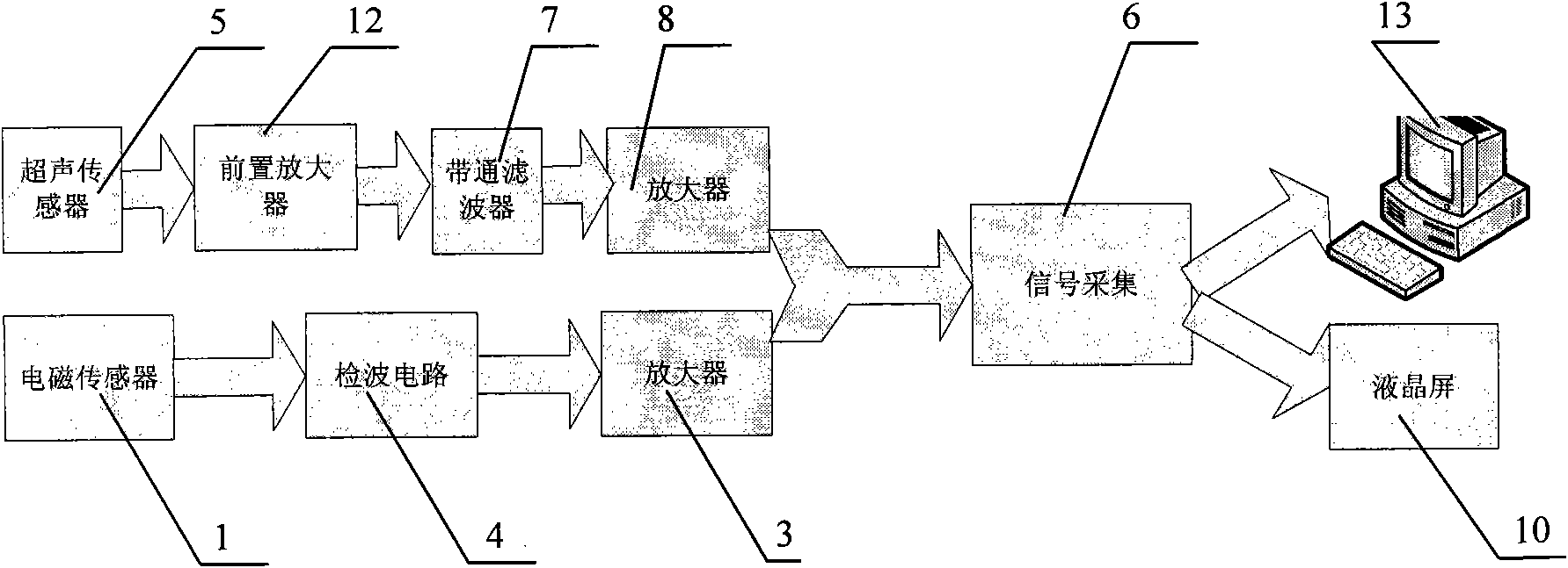
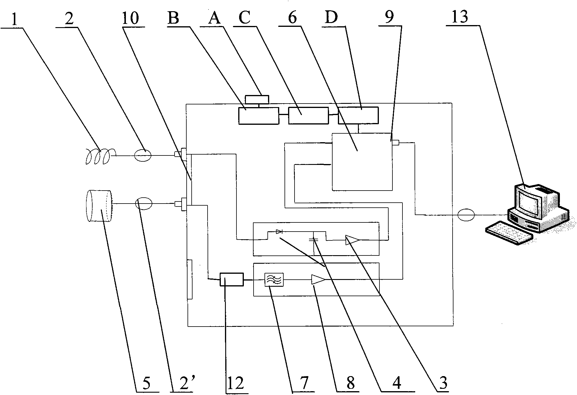
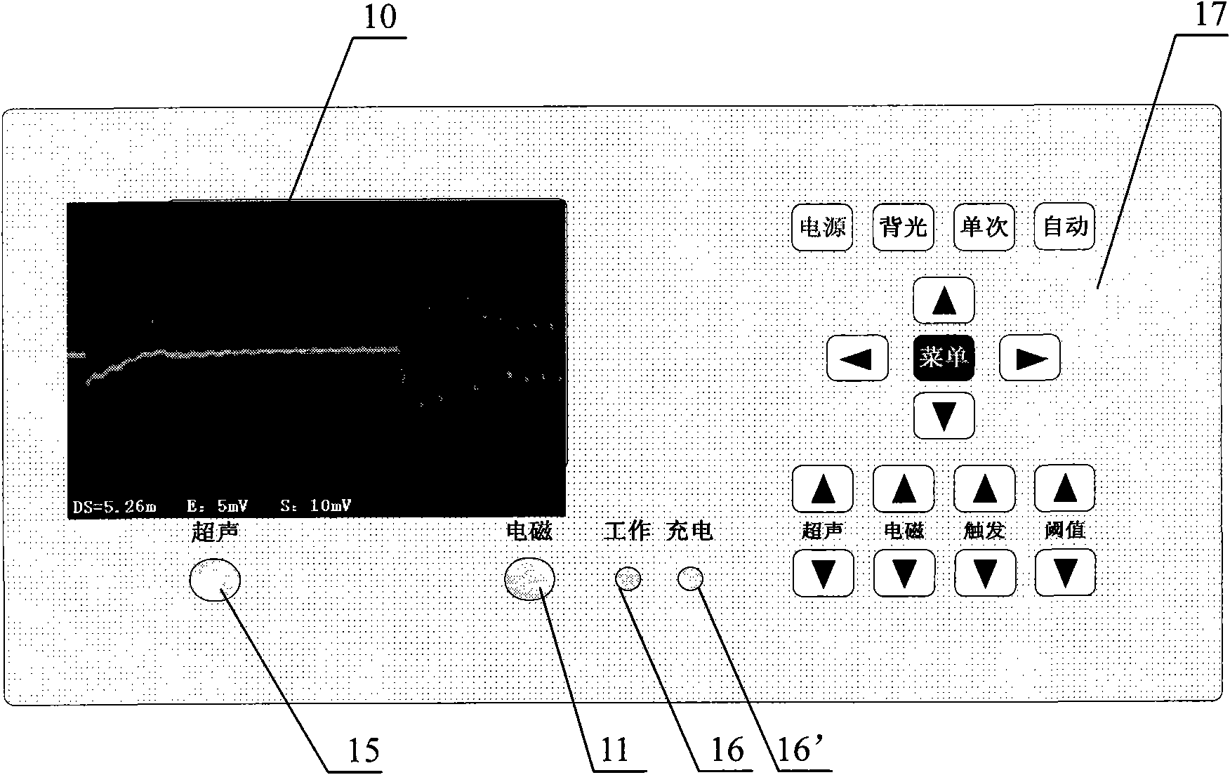
[0056] like figure 2 , Figure 5 As shown, there is a defect 23 in the gas insulated switch 22 of the ground 20, thereby generating a partial discharge. Through the partial discharge detection locator 14, a vibrating contact type resonant ultrasonic sensor 25 combined with a miniaturized narrow-band antenna 21 is used. Mobile resonant ultrasonic sensor 25 with a moving range of 1m 2 ; By observing the variation of the ultrasonic signal amplitude displayed by the partial discharge detection locator 14, move the resonant type ultrasonic sensor 25 up and down, left and right, such as finding that the ultrasonic signal amplitude becomes smaller when it is far away from a certain point, and the ultrasonic signal amplitude increases when approaching , indicating the presence of partial discharge. Stop when the signal amplitude displayed by the partial discharge detection locator 14 is the largest and the distance is the smallest, and the detected position at this time is the rel...
Embodiment 2
[0059] like figure 2 , Image 6 As shown, there is a fault point 33 in the buried cable 30 and a discharge fault occurs. The combination of the resonant contact ultrasonic sensor 31 and the small narrowband antenna 35 is used to connect the resonant contact ultrasonic sensor 31 and the small narrowband antenna 35 respectively. Insert the resonant ultrasonic sensor socket 15 and the electromagnetic sensor socket 11 of the partial discharge detection and locator 14 to detect and locate the partial discharge fault on the buried cable 30. First put the vibration contact type resonant ultrasonic sensor 31 on the ground surface 32, cooperate with the small narrow-band antenna 35, the operator 18 moves the resonant ultrasonic sensor 31 along the direction of the cable by operating the partial discharge detection locator 14, if found in a certain The amplitude of the ultrasonic signal decreases when the point is far away, and increases when it is close to the point, indicating the e...
Embodiment 3
[0061] like figure 2 , Figure 7 As shown, there are overhead lines 46 and 47 in the pole tower 40, wherein there is a corona discharge in the air on the line 46, and the combination of the acoustic emission type resonant ultrasonic sensor 41 and the small narrow-band antenna 45 is used to control the overhead line of the power equipment along the air. Corona discharge faults and insulators are used to detect and locate partial discharge faults. During detection, the acoustic emission type resonant ultrasonic sensor 41 and the small narrowband antenna 45 are respectively connected to the resonant ultrasonic sensor socket 15 and the electromagnetic sensor socket 11 of the partial discharge detection and locator 14 at the same time, and the operator 18 detects and locates the partial discharge by moving Instrument 14, it can be seen that the amplitude of the partial discharge signal displayed on it changes with the change of the distance. For example, if it is found that near ...
PUM
 Abstract
Description
Claims
Application Information
 - R&D
- Intellectual Property
- Life Sciences
- Materials
- Tech Scout
- Unparalleled Data Quality
- Higher Quality Content
- 60% Fewer Hallucinations
Browse by: Latest US Patents, China's latest patents, Technical Efficacy Thesaurus, Application Domain, Technology Topic, Popular Technical Reports.
© 2025 PatSnap. All rights reserved.Legal|Privacy policy|Modern Slavery Act Transparency Statement|Sitemap|About US| Contact US: help@patsnap.com


