Method and device for the adaptive regulation of power

a technology of adaptive regulation and power, applied in the direction of measurement devices, using reradiation, instruments, etc., can solve the problems of unacceptably high signal level, additional measurements, parking lots at sports facilities or shopping centers, etc., to reduce power, reduce signal irregularities in radar detectors, and reduce measurement repetition rate

Inactive Publication Date: 2006-05-25
ROBERT BOSCH GMBH
View PDF7 Cites 77 Cited by
  • Summary
  • Abstract
  • Description
  • Claims
  • Application Information

AI Technical Summary

Benefits of technology

[0005] The present invention minimizes signal irregularities in radar detectors by using an adaptive power control. As soon as it becomes apparent that the interference is unacceptably high due to a heavy traffic density, an appropriate power adaptation is carried out. Once objects have been reliably detected, the measurement repetition rate may be reduced. In addition, the possible detection range does not need to be utilized up to the maximum value; instead, it may be stopped once a limit to be regarded as useful is reached, such as of two to five detected objects, especially as the power requirement increases with the fourth power of the distance. Provided that a ground speed is measurable, at a low speed of less than about 20 to 40 km / h or at standstill, and in the case of far away objects, the power may likewise be reduced by limiting the average power, the measurement repetition frequency, or the maximum distance. The relatively low speed makes it unlikely that objects would appear unexpectedly. If necessary, however, a measurement may also be made in-between, up to the maximum range, in order to secure the intervening space up to the furthest object, and thereby enhance the safety on the whole. The speed information may be obtained from the wheel speeds, from a radar measurement which records the ground speed, or from an SRR (secondary surveillance radar) measurement by estimating stationary objects. While the first two mentioned methods lead to very reliable results, the last-mentioned method additionally requires an exact classification into illusory objects, on the one hand, and tangible moving objects, on the other hand, to attain reliable results. Since in situations of high traffic density and, thus, a high concentration of sensors, the interfering influences increase, in which case the present invention also makes it possible to adaptively reduce the power within a relatively short range, provided that reliably detected objects exist. The present invention makes it possible for the transmitting power to be reduced, thereby facilitating an approval in conformance with UWB (ultra-wide band) criteria. By reducing the transmitting power, the interference immunity may be further enhanced. This means that there is less mutual interference among adjacent vehicles. The reduced transmitting power leads to a lower current consumption, which is beneficial in terms of energy usage. Also, because of the reduction in load, one can expect a longer service life. By applying the approach of the present invention, assuming a maximum distance of 20 m and a breaking off of the emissions in the distance stages 5 m, 10 m or 15 m, the average power could be reduced by 30 db, 15 db, and 6 dB, respectively. Consequently, the spectral density is, of course, also lowered. In addition, the transmitted power could also be lowered by approximately 6 to 20 dB.

Problems solved by technology

In practice, the transmission range is about 20 m. The risk inherent in such systems is that unacceptably high signal levels occur, even in frequency ranges that have been blocked in favor of other services, e.g., frequency ranges that are reserved for radio astronomy or also for radio relay services.
Similar problems arise in large parking lots at sports facilities or shopping centers when, for example, after a big event ends, hundreds of vehicles start moving at the same time and leave the parking lot.
For the most part, these problems only occur when the vehicles are at standstill or traveling at a relatively slow speed.
Furthermore, the spatial proximity of many sensors also causes heavy mutual interference, which, when working with adaptive sensors, increasingly leads to additional measurements being taken, although some objects may have actually already been reliably detected.

Method used


Image

  • Method and device for the adaptive regulation of power
  • Method and device for the adaptive regulation of power
  • Method and device for the adaptive regulation of power

Examples


Embodiment Construction

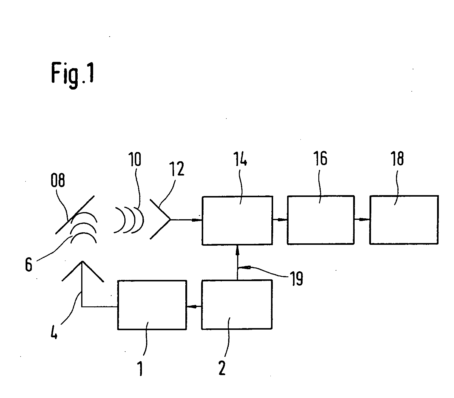
[0013] In a block diagram, FIG. 1 shows a radar device having a correlation receiver as known in the art. A pulse generator 2 induces a transmitting device 1 to emit a transmitted signal 6 via an antenna 4. Transmitted signal 6 impinges on a target object 8, where it is at least partially reflected, and returns to receiver 14. Received signal 10 is received by antenna 12. In this context, antenna 12 and antenna 4 may be identical and be switched between transmitting and receiving operation. Upon receipt of received signal 10 by antenna 12, received signal 10 is routed to receiver 14 and subsequently fed via a filter device having A / D conversion 16 to an evaluation device 18. An exceptional feature of such a radar device, which has a correlation receiver, is that receiver 14 receives a reference signal 20 from pulse generator 2. Received signals 10 received by receiver 14 are mixed in receiver 14 with reference signal 20. The correlation operation makes it possible to infer the dista...


PUM


Abstract

A method and a device for adaptively controlling power in a radar device having a radar transmitter and a radar receiver are provided, in particular for applications in vehicles. The radar signals are emitted, and radar signals reflected off of target objects are received and checked for irregularities. The transmitting power of the radar transmitter is reduced when irregularities occur which are attributable to interference caused by neighboring radar transmitters.

Description

FIELD OF THE INVENTION [0001] The present invention is directed to a method and a device for adaptively controlling power of transmitted signals of a radar detector. BACKGROUND INFORMATION [0002] In the automotive sector, systems which measure the distances and velocities of objects around one's own vehicle by using microwaves and applying the radar principle are in use. These objects can be vehicles which are actively taking part in the highway traffic or some sort of obstacles on or near the road. Keyless remote-entry systems for vehicles (keyless entry / comfort entry / keyless go systems) also make use of these technologies. In the known systems, high-frequency energy is radiated in a frequency range in the gigahertz range, at a mid-frequency of 24,125 GHz and with a two-way bandwidth of several GHz. Typical antennas have a directional characteristic (i.e., an antenna radiation pattern) of 80 degrees*20 degrees. In practice, the transmission range is about 20 m. The risk inherent in...

Claims


Application Information

Patent Timeline
Patent Type & Authority Applications(United States)
IPC IPC(8): G01S13/00G01S7/282G01S13/02G01S13/931
CPCB60T2201/10G01S7/023G01S7/282G01S13/931G01S2007/4013G01S2013/9353G01S2013/9375G01S2013/9378G01S2013/9385G01S2013/93274G01S2013/93272G01S2013/932G01S2013/93271G01S7/4013
Inventor VOIGTLAENDER, KLAUSGAIER, STEFANRUOSS, HANS-OLIVERSEIDEL, JUERGEN
Owner ROBERT BOSCH GMBH
Why Eureka
Try Eureka