Front vertical beam reinforcing plate, right front vertical beam and automobile

A technology for reinforcing plates and front longitudinal beams, applied to vehicle parts, substructure, transportation and packaging, etc., can solve problems such as unsatisfactory ductility of reinforcing plates, excessive structural design performance, and inability to carry collision energy, etc., to achieve easy renewal and improvement , Reduce the risk of bearing deformation, the effect of simple structure

Active Publication Date: 2015-04-01
ZHEJIANG GEELY AUTOMOBILE RES INST CO LTD +1
View PDF5 Cites 5 Cited by
  • Summary
  • Abstract
  • Description
  • Claims
  • Application Information

AI Technical Summary

Problems solved by technology

[0003] At present, the customary way to design car longitudinal beam reinforcement plates is to use simple structural design and steel plates with strong material properties to strengthen them. The lower reinforcing plate is combined, the material usage is large, the material utilization rate is low, the design is bulky, and the structural design performance is relatively redundant; second, although the structure of the suspension reinforcing plate and the longitudinal beam lower reinforcing plate In the process, the mold development cost is not saved, and the bending control of the longitudinal beam is poor during the collision deformation, and the strengthening effect is not significant in essence
In the ODB (frontal 56km / h offset crash test, which requires 40% overlap of the test vehicle to impact the fixed deformable energy-absorbing barrier frontally, and the collision speed is 56km / h), the energy absorption of the right longitudinal beam is a key design requirement. It can reduce the risk of deformation of the left longitudinal beam. However, the current design makes the ductility of the reinforcement plate in the X direction (ie, the longitudinal direction of the longitudinal beam) unsatisfactory, especially in the offset collision under the ODB condition. The longitudinal beam will not be able to bear and absorb the corresponding collision energy due to local bending deformation

Method used


Image

  • Front vertical beam reinforcing plate, right front vertical beam and automobile
  • Front vertical beam reinforcing plate, right front vertical beam and automobile
  • Front vertical beam reinforcing plate, right front vertical beam and automobile

Examples


Embodiment Construction

[0021] In order to further explain the technical means and effects adopted by the present invention to achieve the intended invention purpose, the specific implementation, structure, features and effects of the present invention will be described in detail below in conjunction with the accompanying drawings and preferred embodiments.

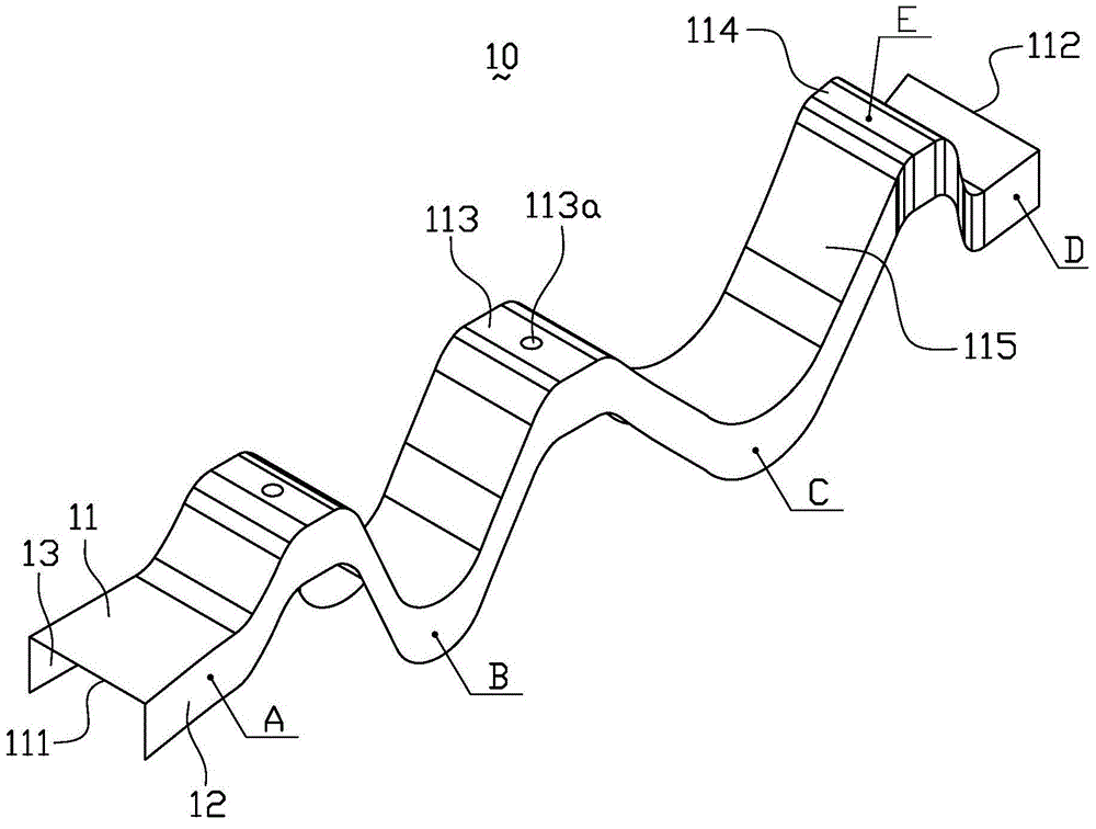
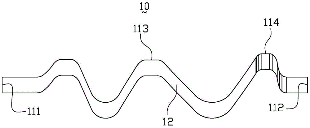
[0022] figure 1 It is a structural schematic diagram of the front longitudinal beam reinforcement plate in the embodiment of the present invention. figure 2 It is a schematic front view of the front longitudinal beam reinforcement plate in the embodiment of the present invention. Please combine figure 1 and figure 2 , the automobile front side beam reinforcement plate 10 of the present invention comprises a reinforcement plate body 11 and a first connection edge 12 and a second connection edge 13 located on both sides of the reinforcement plate body 11, and the reinforcement plate body 11 has a front end of a corresponding longitudinal beam ...


PUM


Abstract

Provided is a front vertical beam reinforcing plate. A front vertical beam comprises a vertical beam outer plate and a vertical beam inner plate. The front vertical beam reinforcing plate comprises a reinforcing plate body and a first connection side and a second connection side which are located on two sides of the reinforcing plate body. The reinforcing plate body is provided with a first end corresponding to the front end of an engine suspension installation point and a second end corresponding to the front end of an auxiliary frame installation hole. The reinforcing plate body extends from the first end to the second end in a concave-convex fluctuation mode to form a plurality of protruding portions. Each protruding portion includes a suspension point installation boss, and the first connection side and the second connection side are used for connecting the vertical beam inner plate and the vertical beam outer plate. The reinforcing plate extends in the concave-convex fluctuation mode to form the plurality of protruding portions, meanwhile suspension point reinforcement and front vertical beam reinforcement are achieved, the right front beam is prevented from being bended and deformed locally in the biasing collision, and left vertical beam bearing deformation risk is reduced. The front vertical beam reinforcing plate is simple in structure, easy to update and improve and capable of reducing development cost.

Description

technical field [0001] The invention relates to a vehicle body structure, in particular to a front side beam reinforcement plate, a right front side beam and an automobile with the right front side beam. Background technique [0002] It is a very common phenomenon to use stiffeners on the front longitudinal beams of automobiles. Its main purpose is to strengthen the mounting points of the engine and protect the engine. At the same time, the application of the stiffeners makes the longitudinal beams have a stepped distribution of performance from front to rear. It is more conducive to the deformation mode control of the longitudinal beam and the absorption of collision energy. [0003] At present, the customary way to design car longitudinal beam reinforcement plates is to use simple structural design and steel plates with strong material properties to strengthen them. The lower reinforcing plate is combined, the material usage is large, the material utilization rate is low,...

Claims


Application Information

Patent Timeline
Patent Type & Authority Applications(China)
IPC IPC(8): B62D21/02
CPCB62D21/02
Inventor 申波祁洪娟管立君张大伟肖海涛孙立志周大永刘卫国吴成明冯擎峰
Owner ZHEJIANG GEELY AUTOMOBILE RES INST CO LTD
Why Eureka
Try Eureka