Biomass gasification furnace convenient for air inlet and ash discharge

A biomass and gasifier technology, applied in the field of household stoves or stoves, can solve the problems of difficulty in ensuring free vibration of a vibrating screen, limitation of the total area of ​​an ash discharge pipe, complicated installation process, etc., so as to shorten the ignition time and facilitate ash discharge. Slag, uniform distribution effect

Active Publication Date: 2015-04-01
FUZHOU SUNSHI XIONGDI IND
View PDF7 Cites 5 Cited by
  • Summary
  • Abstract
  • Description
  • Claims
  • Application Information

AI Technical Summary

Problems solved by technology

However, due to the establishment of the internal ash discharge pipe, according to the requirements of the installation process of the internal ash discharge pipe, the total area of ​​the ash discharge pipe is limited, and the ash discharge effect is poor. Moreover, the design of the air pipe passing through the vibrating screen makes the installation process difficult. Relatively complex, especially for the complex environment in the gasifier furnace, it is difficult to ensure the free vibration of the vibrating screen

Method used


Image

  • Biomass gasification furnace convenient for air inlet and ash discharge
  • Biomass gasification furnace convenient for air inlet and ash discharge
  • Biomass gasification furnace convenient for air inlet and ash discharge

Examples


Embodiment 1

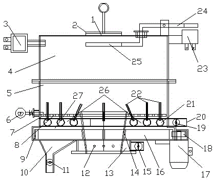
[0039] figure 1 middle;

[0040] The fire closing plate 1 is movably connected with the fire outlet 2, the fire outlet 2 is connected with the upper part 4 of the furnace, the igniter 3 is fixedly connected with the side wall of the upper part 4 of the furnace, the upper part 4 of the furnace is connected with the lower part 5 of the furnace, and the material level sensor 23 is connected with the upper part of the furnace 4 connected, the material level sensing rod 24 is flexibly connected with the furnace upper part 4, and the material level sensing rod 24 is connected with the material level sensing plate 25.

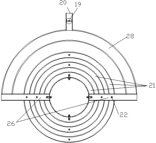
[0041] The annular air duct air inlet 20 is connected with the annular air duct valve 19, the annular air duct valve 19 is connected with the annular air duct 21, the annular air duct 21 is fixedly connected with the furnace inner bottom of the furnace lower part 5, and the annular air duct 21 has a gap with the vibrating screen 7 Connected, the vibrating screen 7 is...

Embodiment 2

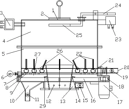
[0044] figure 2 middle;

[0045] Its structure is that the annular air duct 21 is movably connected with the lower part 5 of the furnace, the annular air duct 21 is fixedly connected with the vibrating screen 7, the vibrating screen 7 is under the annular air duct 21 and is movably connected with the lower part 5 of the furnace, and the vibrator 6 is fixed with the vibrating screen 7 Connected, the vibrator 6 is movably connected with the lower part 5 of the furnace. That is, the annular air duct 21 and the vibrating screen 7 vibrate simultaneously. The ash retaining flange 29 is arranged on the feed pipe wall, and the ash retaining flange 29 is above the rotating connection position between the ash scraping wheel 16 and the feed pipe wall, and is used to block the ash from directly entering the rotating connection position from above to reduce jamming. death phenomenon.

[0046] In the two structures of the above schemes, since the outer surface of the annular air duct 21...


PUM


Abstract

The invention discloses a biomass gasification furnace convenient for air inlet and ash discharge. A bottom-top feeding way is adopted. A hearth comprises a feeding pipe, a hearth air inlet device and an ash discharge device, wherein the hearth air inlet device and the ash discharge device are arranged on the bottom inside the hearth and arranged surrounding the feeding pipe or a feeding opening in the hearth; annular air ducts (21) in the hearth air inlet device is arranged above a vibrating sieve (7) in the ash discharge device, and the annular air duct (21) is connected with the vibrating sieve (7). The annular air duct and the vibrating sieve vibrate simultaneously, the annular air ducts and the air pipe also can vibrate simultaneously, so that not only can the uniformity in air feeding in the hearth be favored, but also a good effect of loosening the ash in the hearth can be realized, and the ash can be conveniently discharged.

Description

technical field [0001] The invention belongs to household furnaces or stoves with solid fuels, and relates to a biomass gasification furnace which is beneficial to uniform air intake and ash discharge, and is mainly aimed at improving the device of the annular air duct in the furnace and the ash discharge method. Background technique [0002] At present, only one annular air duct is installed in the furnace of the biomass gasifier that uses annular air duct to blow air, which will cause uneven wind field and air pressure in the furnace. If the furnace is to work normally, the local temperature of the fuel in the furnace will exceed 800 degrees, which is easy Generate slagging (fuel slagging temperature is generally 680 degrees), because slagging will affect the ventilation performance of the furnace, so that the gasifier cannot work continuously for a long time. Therefore, there is a need for a furnace air intake and ash discharge device that is conducive to discharging the ...

Claims


Application Information

Patent Timeline
IPC IPC(8): F24B1/19F24B1/191
Inventor 孙清刚陆振邦孙吉章
Owner FUZHOU SUNSHI XIONGDI IND
Why Eureka
Try Eureka