
High-precision time synchronization method and system applied to electric energy meter

A high-precision, electric energy meter technology, applied in the field of high-precision time synchronization methods and systems, can solve problems such as batch errors of electric meters, inaccurate production time synchronization system time, difficulty in ensuring complete smoothness of network physical channels, etc., to ensure accuracy Effect

Inactive Publication Date: 2015-04-01
ZHUHAI ZHONGHUI MICROELECTRONICS
View PDF8 Cites 5 Cited by
  • Summary
  • Abstract
  • Description
  • Claims
  • Application Information

AI Technical Summary

Problems solved by technology

[0003] However, because the time accuracy and real-time performance of the computer itself is not high, and it is easy to be manually modified, it is difficult to guarantee the reliability of the system time; the network of the production system generally uses the public network, due to network delays or network physical channels. It is difficult to ensure complete unblocking, so the network time is also difficult to guarantee the reliability of the production timing system
Due to the incomplete reliability of computer time and network time, the time inaccuracy of the production timing system is inaccurate, which often leads to batch errors in the production of electric meters, which seriously affects production efficiency. Therefore, an accurate and reliable electric energy meter timing system is imminent.

Method used


Image

  • High-precision time synchronization method and system applied to electric energy meter
  • High-precision time synchronization method and system applied to electric energy meter
  • High-precision time synchronization method and system applied to electric energy meter

Examples


Embodiment Construction

[0029] The application will be further described in detail below in conjunction with the accompanying drawings and embodiments. It should be understood that the specific embodiments described here are only used to explain related inventions, rather than to limit the invention. It should also be noted that, for the convenience of description, only the parts related to the related invention are shown in the drawings.

[0030] It should be noted that, in the case of no conflict, the embodiments in the present application and the features in the embodiments can be combined with each other. The present application will be described in detail below with reference to the accompanying drawings and embodiments.

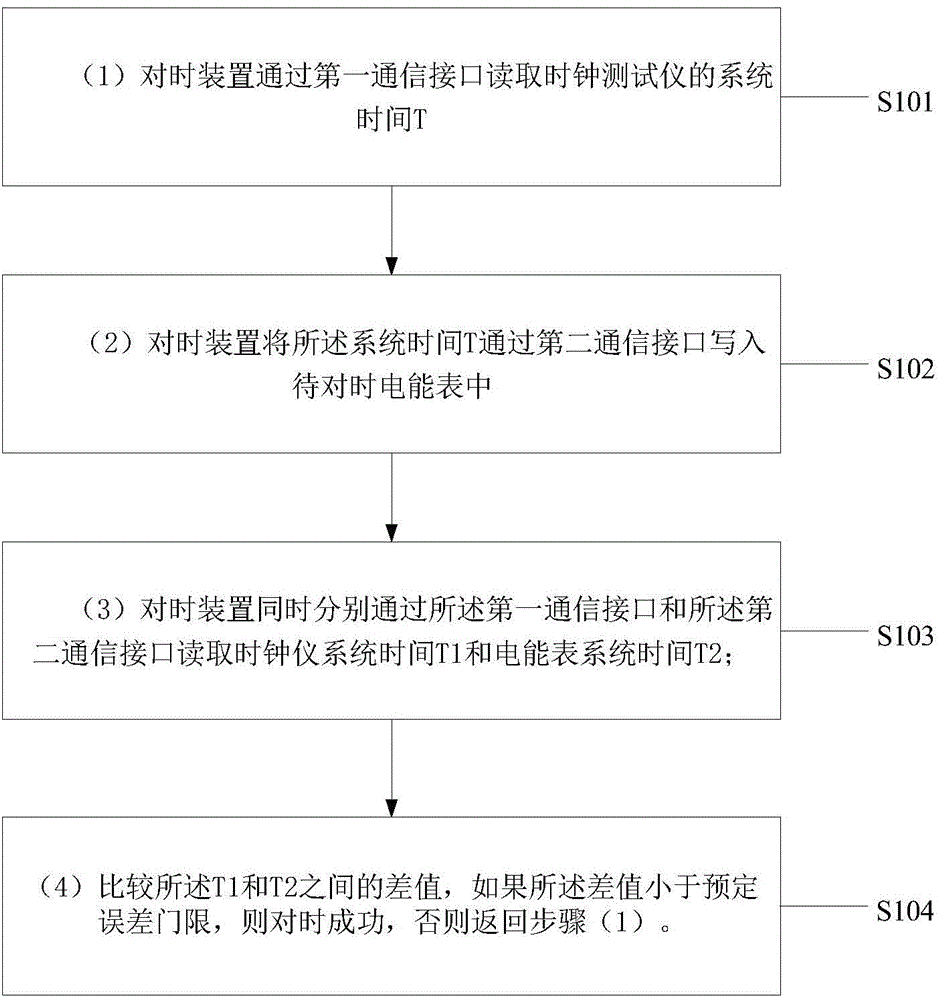
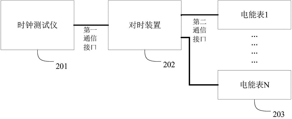
[0031] Such as figure 1 Shown, a kind of high-precision timing method applied in the electric energy meter, the system of described high-precision timing includes: clock tester, timing device and electric energy meter, described method comprises:

[0032] (S101) The time sy...


PUM


Abstract

The invention relates to a high-precision time synchronization method and system applied to an electric energy meter. The high-precision time synchronization system includes a clock tester, a timing synchronization device and an electric energy meter. The time synchronization method comprises the following steps that: (1) the timing synchronization device reads system time T of the clock tester through a first communication interface; (2) the timing synchronization device writes the system time T to an electric energy meter to be subjected to time synchronization through a second communication interface; (3) the timing synchronization device reads system time T1 of the clock tester and system time T2 of the electric energy meter respectively through the first communication interface and the second communication interface; and (4) the difference value of T1 and T2 is obtained through comparison, if the difference value is smaller than a predetermined error threshold, time synchronization is successful, otherwise, the method returns to step (1). With the high-precision time synchronization method and system can ensure the reliability of the time of a terminal system to be subjected to time synchronization and ensure the accuracy of time synchronization.

Description

technical field [0001] The present application relates to the technical field of instruments and meters, in particular to a high-precision time synchronization method and system applied to electric energy meters. Background technique [0002] In the prior art, with the popularization of tiered electricity prices, higher requirements are put forward for the clock accuracy of the electric energy meter. The absolute error of the calendar clock is not allowed to exceed 3 seconds, and the existing electric energy meter is produced and inspected. The time method generally uses computer time or network time as the basis. [0003] However, due to the low accuracy and real-time performance of the computer's built-in time, and it is easy to be manually modified, it is difficult to guarantee the reliability of the system time; the network of the production system generally uses the public network, due to network delays or network physical channels. It is difficult to ensure complete s...

Claims


Application Information

Patent Timeline
Patent Type & Authority Applications(China)
IPC IPC(8): G01R35/04
Inventor 任智仁薛雷周宣周杰文韩潇俊
Owner ZHUHAI ZHONGHUI MICROELECTRONICS
Learn More