Drive swing shaft sleeve

A technology of oscillating shafts and shaft sleeves, which is applied in the field of packaging units, can solve the problems of reduced production efficiency, damage to the driving arm, poor wear resistance and poor strength, etc., and achieve the effects of improving the strength of the workpiece, improving the structure, and increasing the driving torque

Inactive Publication Date: 2015-04-08
HEFEI SANGUAN PACKING SCI & TECH
View PDF6 Cites 1 Cited by
  • Summary
  • Abstract
  • Description
  • Claims
  • Application Information

AI Technical Summary

Problems solved by technology

[0002] There are many mechanisms to realize the drive, but most of them are direct drive, which cannot satisfy the current hopper door drive, and the drive arm structure is a linear structure, which is poor in wear resistance and strength, which is not conducive to long-term use. Causes damage to the driving arm, which is not conducive to the realization of industrial automation, reduces production efficiency, and increases production costs

Method used


Image

  • Drive swing shaft sleeve
  • Drive swing shaft sleeve

Examples


Embodiment Construction

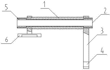
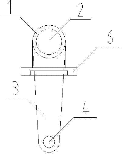
[0013] A drive swing sleeve shaft, including a shaft sleeve (1), characterized in that ball bearings (5) are installed on both sides of the shaft hole (2) of the shaft sleeve (1), and the shaft sleeve (1) A drive connecting rod (3) is welded on one side, and a drive disc (6) is welded on the other side of the bushing (1). The drive disc (6) is a disc structure and has a cylindrical stepped hole. The drive connecting rod (3) has a circular arc structure at both ends of the connecting rod, and a connecting hole (4) is opened at the lower end.

[0014] The driving source pushes the drive connecting rod (3). Since the bushing (1) is connected to the round shaft through the ball bearing (5), the driving connecting rod (3) rotates around the round shaft to drive the bushing (1) to rotate. At this time The drive disc (6) fixed on the other end of the shaft sleeve (1) also rotates together with the shaft sleeve (1), and the drive disc (6) can drive other structures to operate.


PUM


Abstract

The invention provides a drive swing shaft sleeve. The drive swing shaft sleeve comprises a shaft sleeve body and is characterized in that ball bearings are arranged on the two sides of a shaft hole of the shaft sleeve body; a driving connecting rod is welded to one side of the shaft sleeve body, and a driving disc is welded to the other side of the shaft sleeve body and is of a disc structure; and a cylindrical step hole is formed in the driving disc, and a connecting hole is formed in the lower end of the driving connecting rod. The drive swing shaft sleeve has the advantages that the drive problem in conversion from the transverse motion to the axial motion is solved, the drive torque is increased and the swing arm motion around a shaft is achieved in an optimization manner; the shaft sleeve is mainly of a rounded angle structure , stress concentration is reduced, and the strength of a product is improved; and the drive swing shaft sleeve is simple in structure and convenient to mount, the production efficiency is improved, and the production cost is reduced.

Description

technical field [0001] The invention relates to the field of a packaging unit, in particular to a driving swing sleeve. Background technique [0002] There are many mechanisms to realize the drive, but most of them are direct drive, which cannot satisfy the current hopper door drive, and the drive arm structure is a linear structure, which is poor in wear resistance and strength, which is not conducive to long-term use. Causes damage to the driving arm, is not conducive to the realization of industrial automation, reduces production efficiency, and increases production costs. Contents of the invention [0003] In order to solve the above problems, a driving swing sleeve is provided. [0004] Its main implementation scheme is as follows: [0005] A drive oscillating bushing, comprising a bushing, characterized in that ball bearings are installed on both sides of the shaft hole of the bushing, a drive link is welded on one side of the bushing, and a drive link is welded on...

Claims


Application Information

Patent Timeline
Patent Type & Authority Applications(China)
IPC IPC(8): B65B35/02
CPCB65B35/02B65B65/02
Inventor 李进陈静张宇传唐永宾孙永军
Owner HEFEI SANGUAN PACKING SCI & TECH
Why Eureka
Try Eureka