Level shift circuit based on low voltage tube

A technology of level shift circuit and low voltage tube, which is applied in the fields of logic circuit coupling/interface, logic circuit, and logic circuit interface device using field effect transistors. The effect of solving the withstand voltage problem

Pending Publication Date: 2019-02-26
浙江航芯源集成电路科技有限公司
View PDF0 Cites 1 Cited by
  • Summary
  • Abstract
  • Description
  • Claims
  • Application Information

AI Technical Summary

Problems solved by technology

Compared with using low-pressure tubes, using high-pressure tubes has many disadvantages: suc

Method used


Image

  • Level shift circuit based on low voltage tube
  • Level shift circuit based on low voltage tube
  • Level shift circuit based on low voltage tube

Examples


Example Embodiment

[0027] The embodiments of the present invention are described in detail below, wherein the same or similar reference numerals represent the same or similar elements or elements with similar functions throughout. The following embodiments described with reference to the drawings are exemplary, and are only used to explain the present invention and cannot be used as a limitation to the present invention.

[0028] Those skilled in the art can understand that, unless otherwise defined, all terms (including technical terms and scientific and technological terms) used herein have the same meanings as commonly understood by those of ordinary skill in the art to which the present invention belongs. It should also be understood that terms such as those defined in general dictionaries should be understood to have meanings consistent with the meanings in the context of the prior art, and unless defined as here, idealized or overly formal meanings will not be used To explain.

[0029] The pre...


PUM


Abstract

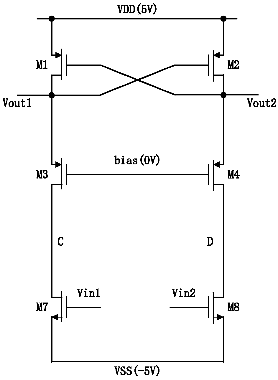
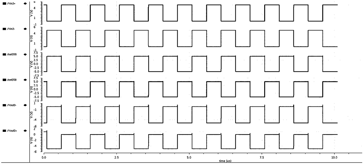
The invention provides a level shift circuit based on a low voltage tube. The circuit comprises an input stage circuit for receiving an inverted input signal, a load stage circuit with a positive feedback structure, and a clamp-level circuit consisting of a P tube voltage protection clamp circuit and an N tube voltage protection clamp circuit. The steady-state voltage of an input device and a drain terminal of a load device can be adjusted by adjusting a width and length ratio of a clamp device so as to control the voltage applied to the device to ensure that the voltage varies within an allowable range.

Description

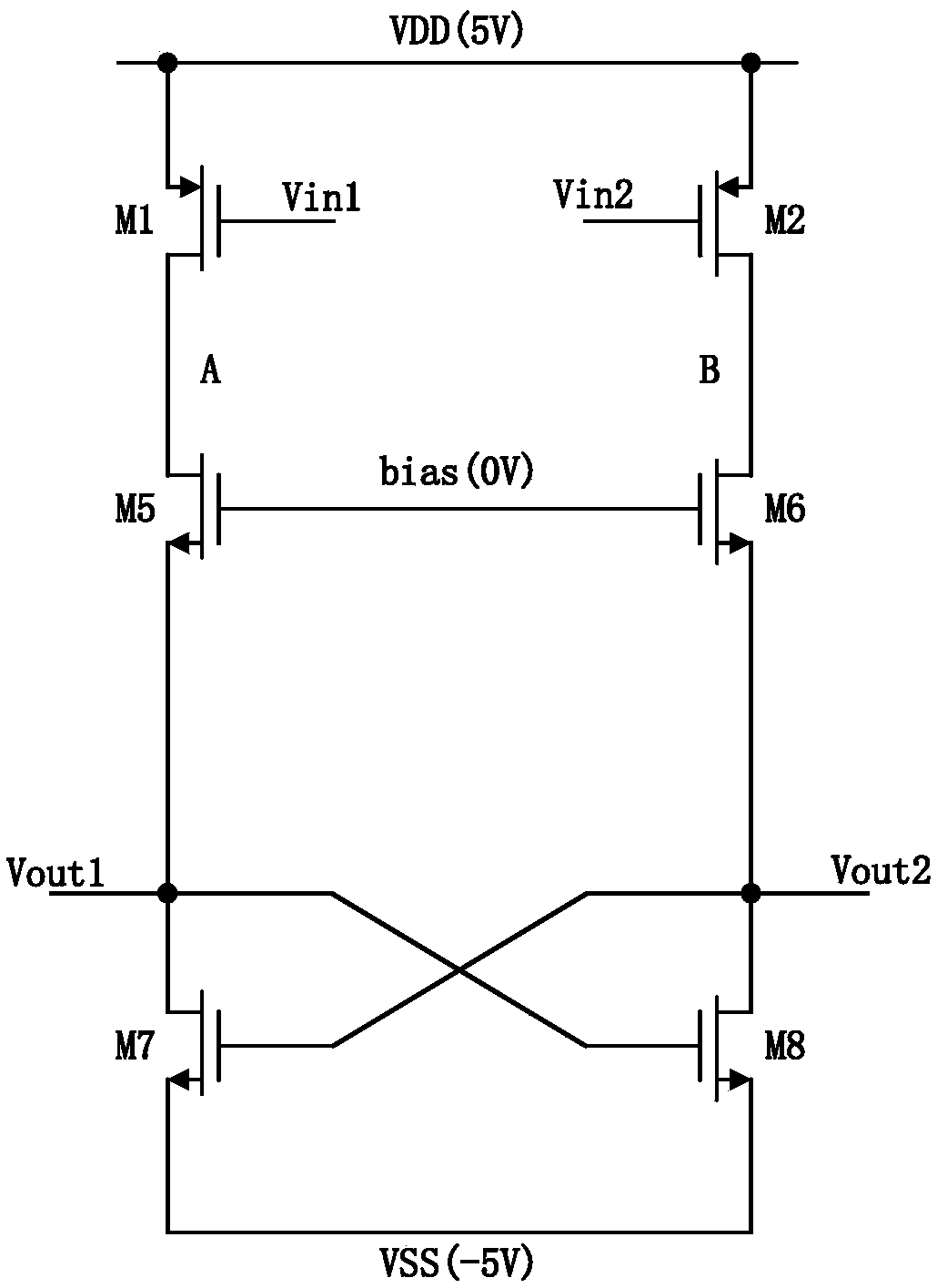
technical field [0001] The invention relates to the field of integrated circuits, more specifically, it relates to a level shift circuit based on a low voltage tube. Background technique [0002] To realize the conversion of positive voltage logic (0V, 5V) to negative voltage logic (-5V, 0V), generally use such as figure 1 The circuit configuration shown. There is an inverter connected between the input port Vin1 and Vin2, so when Vin1 is low level (0V), Vin2 is high level (5V), and when Vin1 becomes high level (5V), Vin2 becomes Low level (0V). The gates of the transistors M5 and M6 are connected and grounded (0V), and they can clamp the upper limit of the output voltage to about 0V. M7 and M8 are a gate-drain cross-connected positive feedback structure, so that the two output terminals quickly reach high and low levels and reach a stable state. [0003] figure 1 The working state of the middle circuit is described as follows: When Vin1 changes from high level (5V) to ...

Claims


Application Information

Patent Timeline
IPC IPC(8): H03K19/0175H03K19/0185
CPCH03K19/017509H03K19/018507
Inventor 但理张凯达陈华吴家宇
Owner 浙江航芯源集成电路科技有限公司
Why Eureka
Try Eureka