Spinning reel

A reel and textile technology, applied in the field of auxiliary accessories for textile machines, can solve the problems of inconvenient installation, difficult to correct, limited space at the elliptical swivel, and achieve the effects of convenient installation, concentrated and accurate traction direction, and material saving

Inactive Publication Date: 2015-04-08
桐梓县创兴自动化设备有限公司
View PDF12 Cites 0 Cited by
  • Summary
  • Abstract
  • Description
  • Claims
  • Application Information

AI Technical Summary

Problems solved by technology

Especially at the elliptical swivel, if the guiding effect is not done well at the beginning, it will be difficult to correct the subsequent lines. However, the space at the elliptical swivel is limited, and installing a specific guide wheel will cause installation inconvenience

Method used


Image

  • Spinning reel
  • Spinning reel

Examples


Embodiment Construction

[0020] The present invention will be described in further detail below by means of specific embodiments:

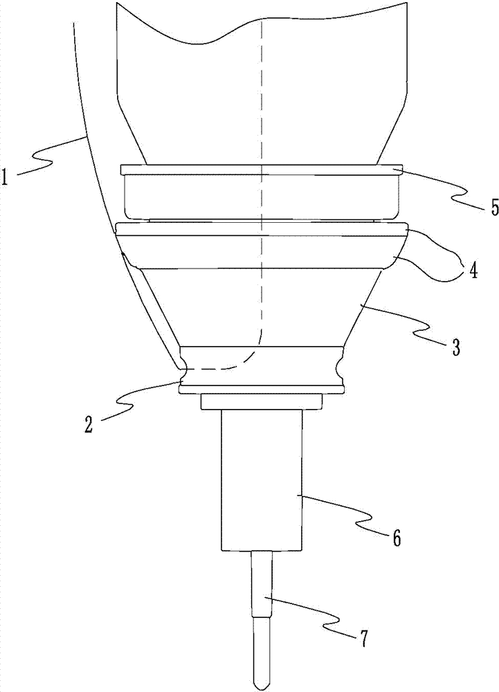
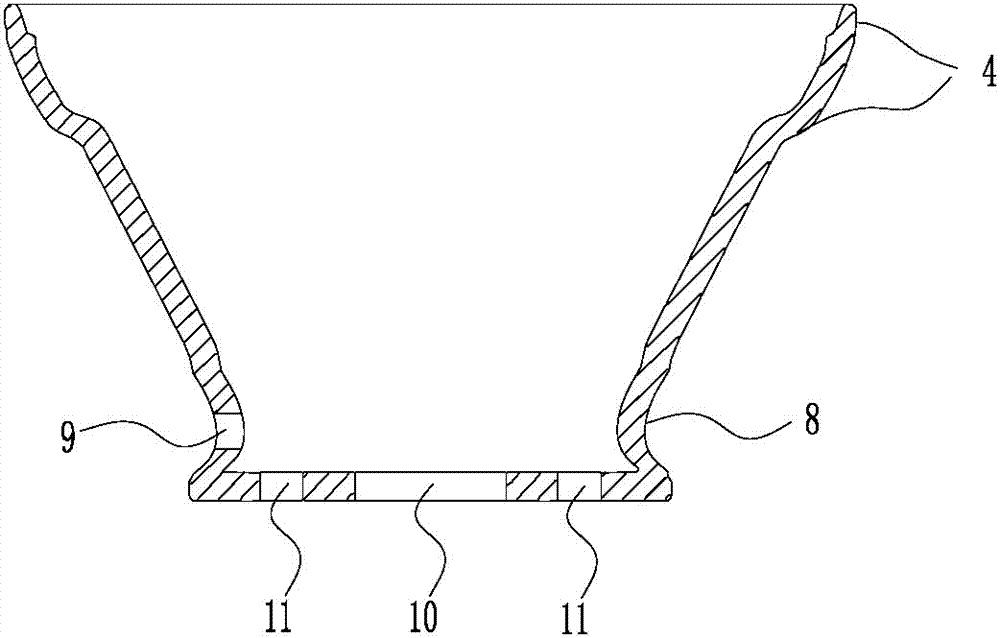
[0021] The reference signs in the drawings of the description include: line 1, lower curved block 2, middle taper sleeve 3, ring platform 4, upper support ring 5, mounting seat 6, connecting shaft 7, indentation area 8, through hole 9, opening Hole 10, winding hole 11.

[0022] Such as figure 1 As shown, the utility model textile winding 1 wheel includes an elliptical swivel body and a support sleeve arranged below the elliptical swivel body, and the lower part of the elliptical swivel body is rotatably connected with the inner wall of the support sleeve through a bearing.

[0023] Bearings can be set using existing basic structures, such as rolling bearings including outer rings, inner rings, rolling elements and cages.

[0024] The supporting sleeve includes an upper support ring 5, a middle taper sleeve 3 and a lower curved block 2 arranged in sequence from top to bo...


PUM


Abstract

The invention relates to an auxiliary accessory for textile machinery, in particular to a spinning reel comprising an elliptical rotor and a supporting sleeve disposed below the elliptical rotor. The supporting sleeve comprises an upper carrier ring, a middle tapered sleeve and a lower cranked block arranged in order from top to bottom. The elliptical rotor is connected with a power mechanism through a connecting shaft. The connecting shaft sequentially passes the axial centers of the lower cranked block, the middle tapered sleeve and the upper carrier ring and is connected to the lower portion of the elliptical rotor. The middle tapered sleeve is in the shape of a funnel with big end up. The middle of the lower cranked block is provided with a circular recessed area. A bearing is disposed between the upper carrier ring and the elliptical rotor. The elliptical rotor is internally provided with a cavity whereby the upper and lower portions of the elliptical portion are communicated. The circular recessed area is provided with a through hole communicated with the cavity. The defect that a guide mechanism is inconvenient to mount at the elliptical rotor is overcome, and the spinning reel is convenient to mount and has certain guidance for a thread.

Description

technical field [0001] The invention relates to an auxiliary accessory for a textile machine, in particular to a textile winding wheel. Background technique [0002] Commonly used reels in textile machinery, generally one thread end of the thread is tied to the top of the reel, and the other thread end of the thread is pulled by a distant traction mechanism. When winding the thread on the reel, the power mechanism drives the reel to rotate to wind the thread onto the reel; on the contrary, when going on and off the reel, the thread needs to be led away by the traction mechanism. The reel will spin in the opposite direction. [0003] Existing reels are divided into an elliptical swivel for winding and a supporting mechanism for supporting the rotation of the swivel. The supporting mechanism and the elliptical rotating body adopt bearings to realize the movable connection between the two, such as a spinning wheel bearing disclosed in Chinese patent CN202531634U, which includ...

Claims


Application Information

Patent Timeline
Patent Type & Authority Applications(China)
IPC IPC(8): B65H75/18
Inventor 王满波
Owner 桐梓县创兴自动化设备有限公司
Why Eureka
Try Eureka