Uniform water distributor with grooved rotor
A technology of distribution device and grooved wheel, which is applied in the direction of processing textile material equipment configuration, etc., can solve the problems that the water distribution device cannot disperse water evenly, and the water distribution device cannot further increase the distribution speed, etc.
- Summary
- Abstract
- Description
- Claims
- Application Information
AI Technical Summary
Problems solved by technology
Method used
Image
Examples
Embodiment 1
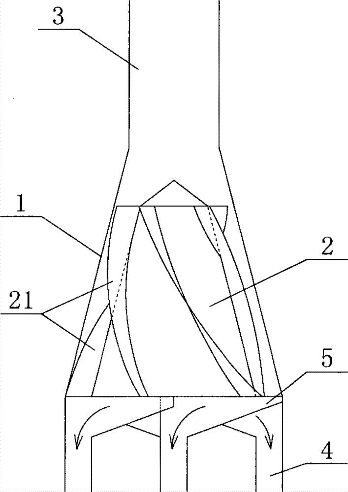
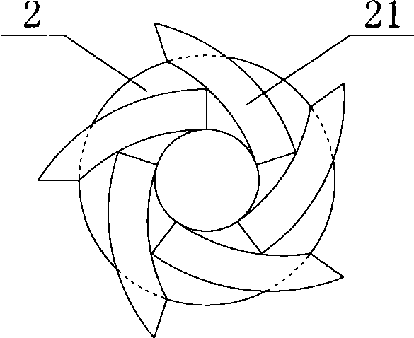
[0036] Such as Figure 1-2 As shown, the groove wheel type water distribution device according to Embodiment 1 of the present invention includes a separation cylinder 1 and a cone 2 located inside the separation cylinder 1. The inner wall of the separation cylinder 1 is conical, and the top of the separation cylinder 1 The center is connected with the vertically installed water inlet pipe 3, the cone 2 is coaxially arranged with the separation cylinder 1, and several evenly arranged spiral blades 21 are arranged on the surface of the cone 2, and the outside of the spiral blade 21 The edge is close to but not in contact with the inner wall of the separation drum 1 .
[0037] A plurality of equally divided separation grooves 5 are arranged around the bottom circumference of the separation drum 1 , each separation groove 5 is arc-shaped, and the bottom or side surface of each separation groove 5 is connected to a water outlet pipe 4 .
[0038] The separation tank 5 is located at...
Embodiment 2
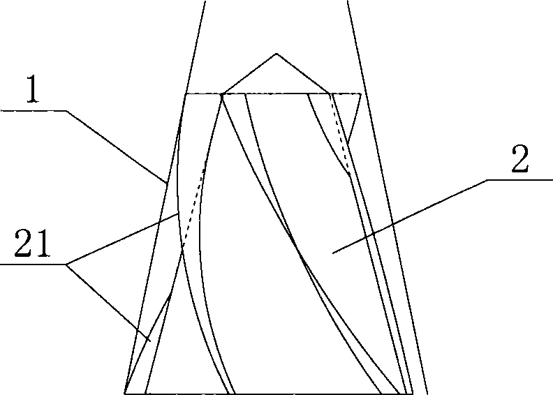
[0042] Such as Figure 3-4 As shown, the differences between this embodiment and Embodiment 1 are:
[0043] The width of the spiral blade 21 gradually decreases from top to bottom, and the taper of the cone 2 is greater than the taper of the inner wall of the separation cylinder 1, so that the distance between the cone 2 and the inner wall of the separation cylinder gradually decreases from top to bottom. Small, to maintain the deflection pressure of the water flow on the helical blade 21, increase the rotational speed of the cone 2, and then more evenly distribute the water in the water inlet pipe.
Embodiment 3
[0045] Such as Figure 5-6 As shown, the differences between this embodiment and Embodiment 1 are:
[0046] The separation groove 5 is located outside the bottom of the separation cylinder 1, and the outer side of each separation groove 5 extends outward along the direction in which the cone 2 rotates, and the outlet pipe 4 is connected to the outer surface of the separation groove 5. Remote connectivity.
[0047] The cone 2 is an active rotating structure, the center of the bottom of the cone 2 is connected to a drive shaft, the drive shaft is driven by a mechanical device, the drive shaft drives the cone 2 to rotate, and then the spiral blade 21 on the surface of the cone 2 The water in the water inlet pipe 3 is evenly distributed.
[0048] Through the groove wheel type water distribution device designed in the first to third embodiments above, when the water enters the separation cylinder 1 from the water inlet pipe 3, it will drive the spiral blade 21 to make the cone 2 ro...
PUM
 Abstract
Description
Claims
Application Information
 - R&D
- Intellectual Property
- Life Sciences
- Materials
- Tech Scout
- Unparalleled Data Quality
- Higher Quality Content
- 60% Fewer Hallucinations
Browse by: Latest US Patents, China's latest patents, Technical Efficacy Thesaurus, Application Domain, Technology Topic, Popular Technical Reports.
© 2025 PatSnap. All rights reserved.Legal|Privacy policy|Modern Slavery Act Transparency Statement|Sitemap|About US| Contact US: help@patsnap.com


