A drying kiln device

A drying kiln and drying room technology, which is applied in the direction of heating devices, drying, drying machines, etc., can solve problems such as the utilization of hot oil furnace gas, reduce energy consumption, prevent quality accidents, and improve The effect of heating capacity

Active Publication Date: 2017-01-04
FUJIAN YONGAN FORESTRY GRP CO LTD
View PDF16 Cites 0 Cited by
  • Summary
  • Abstract
  • Description
  • Claims
  • Application Information

AI Technical Summary

Problems solved by technology

Its research also did not mention the utilization of hot oil furnace gas

Method used


Image

  • A drying kiln device

Examples


Embodiment Construction

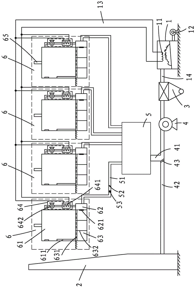
[0031] Such as figure 1 As shown, a drying kiln device includes an organic heat carrier furnace 1, a furnace gas discharge chimney 2, a multi-tube dust collector 3, a boiler induced draft fan 4, a furnace gas buffer chamber 5, and multiple drying room devices 6;

[0032] The organic heat carrier furnace 1 has a steam generator 11 and a boiler blower 12; the steam generator 11 is connected to a heating pipeline 13, and the heating pipeline 13 is respectively connected to each drying room device 6; The furnace gas outlet 14 of the carrier furnace 1 is connected to the multi-pipe dust collector 3;

[0033] The multi-tube dust collector 3 is connected to the boiler induced draft fan 4;

[0034] The air duct of the boiler induced draft fan 4 forms two branches 41, 42, respectively connected to the furnace gas buffer chamber 5 and the furnace gas discharge chimney 2; the boiler induced draft fan 4 is connected to the furnace gas discharge chimney The air duct 42 of 2 is provided ...


PUM


Abstract

A dry kiln device comprises an organic heat-transfer material furnace, a furnace gas exhausting chimney, a multi-tube dust cleaner, a boiler draught fan, a furnace gas buffer chamber and a plurality of drying chamber devices. The organic heat-transfer material furnace is provided with a vapor generator and a boiler blower. The vapor generator is connected with a heat supply pipeline which is connected with the drying chamber devices. A furnace gas outlet of the organic heat-transfer material furnace is connected with the multi-tube dust cleaner connected to the boiler draught fan. An air pipe of the boiler draught fan is divided into two branches which are respectively connected to the furnace gas buffer chamber and the furnace gas exhaust chimney. The boiler draught fan is connected with the furnace gas exhaust chimney through the air pipe provided with a large air door. The furnace gas buffer chamber is connected with the drying chamber devices respectively. The dry kiln device has the advantages that vapor drying and smoke dying are performed to improve drying efficiency and reduce energy consumption.

Description

[0001] 【Technical field】 [0002] The invention relates to a drying kiln device, which is suitable for drying treatment of raw materials such as wood, Chinese herbal medicine, and briquettes. [0003] 【Background technique】 [0004] The method of directly using furnace gas to dry raw materials has long existed, such as brick drying in brick-making enterprises, ceramic raw material drying, barbecue, baked cakes, etc.; there is also a flash dryer for extremely flammable wood fiber Drying technology has also been widely used in medium-density fiberboard production enterprises and has been industrialized. It uses the characteristics that the initial moisture content of wood fiber is as high as 80% to 100% and is not easy to burn. It is sprayed on the hot flue gas. A small amount of flue gas sparks are sprayed out. If there are still sparks reaching the position of the dry fiber behind the drying pipe, the method of spraying is used to stop the fire from happening. The drying and d...

Claims


Application Information

Patent Timeline
Patent Type & Authority Patents(China)
IPC IPC(8): F26B23/10F23J15/02
Inventor 王永闽吴景贤董永平吴祖顺陈建新刘翔晖
Owner FUJIAN YONGAN FORESTRY GRP CO LTD
Why Eureka
Try Eureka