Connector for wiring network

A technology of connectors and optical fiber connectors, which is applied in the direction of connection, parts of connection devices, contact parts, etc., can solve problems such as poor contact and inability to take out chips conveniently, and achieve the effect of convenient replacement

Inactive Publication Date: 2015-04-08
CHINA AVIATION OPTICAL-ELECTRICAL TECH CO LTD
View PDF6 Cites 0 Cited by
  • Summary
  • Abstract
  • Description
  • Claims
  • Application Information

AI Technical Summary

Problems solved by technology

[0003] The purpose of the present invention is to provide a connector for wiring network, which solves the problem of poor contact of the connector in the prior art due to the weak connection of the chip, and can not conveniently replace the chip when replacing the chip. Take out technical issues

Method used


Image

  • Connector for wiring network
  • Connector for wiring network
  • Connector for wiring network

Examples


Embodiment Construction

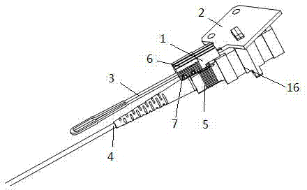
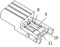
[0017] An embodiment of a connector for a distribution network, such as Figure 1-4 Shown: the connector for distribution network in this embodiment, comprises intelligent connector 1, optical fiber connector 5 and adapter 16, and one end of optical cable 4 and optical fiber connector 5 is mated to realize optical signal connection, and the contact of intelligent connector The pins of the component are mated with the printed board 2 to realize electrical connection, and the other end of the optical fiber connector 5 is connected to the adapter 16 to realize the communication of the entire distribution network signal. The blocking structure that prevents the chip from moving in a direction parallel to the mating surface and detaching from the mating surface, the thickness of the blocking structure extends along the direction perpendicular to the mating surface, the blocking structure here is formed by the side wall 9 of the mounting seat and the protrusion Composed of block 11,...


PUM


Abstract

The invention discloses a connector for a wiring network. The connector for the wiring network comprises a smart connector, an optical fiber connector and an adapter, wherein the smart connector comprises a shell, a chip and a contact; a matching surface corresponding to the bottom surface of the chip and used for supporting and matching is arranged on the connector shell; a stop structure for preventing the chip from moving along the direction parallel to the matching surface so as to be separated from the matching surface is arranged on the periphery of the matching surface on the connector shell in a protruding way; an elastic pressing piece applying pressing force toward the matching surface to the chip is arranged on the connector shell; an unlock operation port is formed in the surface of the connector shell, and provides an inlet for a force application object for pushing the bottom surface of the chip to separate from the matching surface; a taking and discharging port communicated with the unlock operation port through a channel is formed in the matching surface, and provides an outlet for the force application object to stretch out and continuously push the chip to overcome the elasticity of the elastic pressing piece so as to be released from the limit of the stop structure. Therefore, the reliable installation of the chip is effectively ensured, and meanwhile, the chip can be replaced conveniently.

Description

technical field [0001] The invention relates to the field of connectors, in particular to a connector for wiring networks. Background technique [0002] Existing connectors for wiring networks include smart connectors, fiber optic connectors and adapters. One end of the fiber optic connector is movably connected to the smart connector, and the other end is movably mated to the adapter. The smart connector includes a shell, a chip, a contact The connector housing is provided with a matching surface for matching and supporting the position of the bottom surface of the chip, and the contact has pins for connecting with the printed board, and the chip needs to be installed during use. The Chinese patent No. 200810304328.7 discloses a chip mounting structure. The structure has a housing, including a mounting seat and a chip. The opening is pushed into the chip mounting position, and the chip can be fixed in the up and down direction by other components, but the chip is easy to c...

Claims


Application Information

Patent Timeline
Patent Type & Authority Applications(China)
IPC IPC(8): H01R13/639H01R13/633H01R13/52H01R13/24G02B6/38
CPCG02B6/38H01R13/24H01R13/2464H01R13/52H01R13/633H01R13/639
Inventor 孙亚磊李小卫王金殿
Owner CHINA AVIATION OPTICAL-ELECTRICAL TECH CO LTD
Why Eureka
Try Eureka