A compressor valve
A technology for compressors and air valves, which is applied in the field of compressor air valves, which can solve problems such as large impact force and shedding of the protective layer, and achieve the effects of improving service life, increasing service life, and reducing viscous force
- Summary
- Abstract
- Description
- Claims
- Application Information
AI Technical Summary
Problems solved by technology
Method used
Image
Examples
Embodiment 1
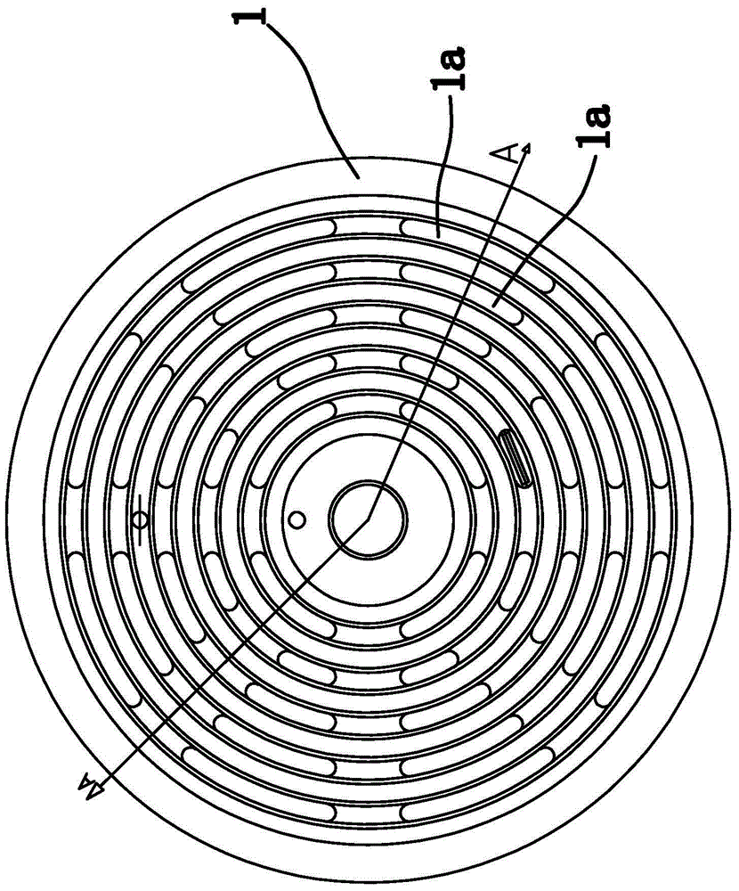
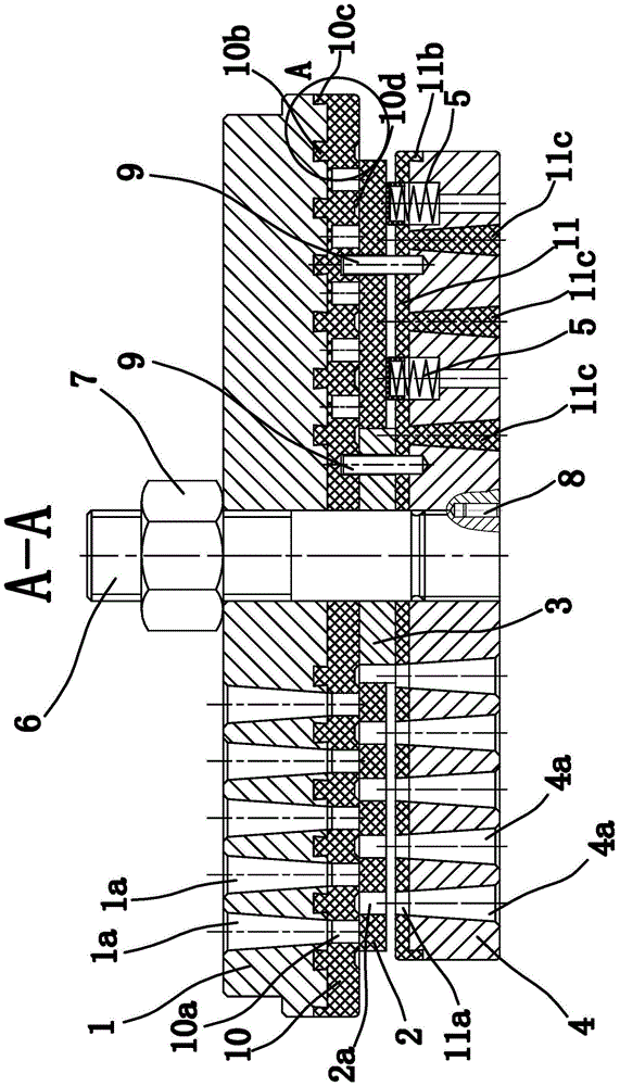
[0043] Such as figure 1 with figure 2 As shown, the compressor air valve is an open air valve, which is composed of a valve seat 1, a valve plate 2, a guide sleeve 3, a lift limiter 4, a spring 5, a bolt 6 and the like.
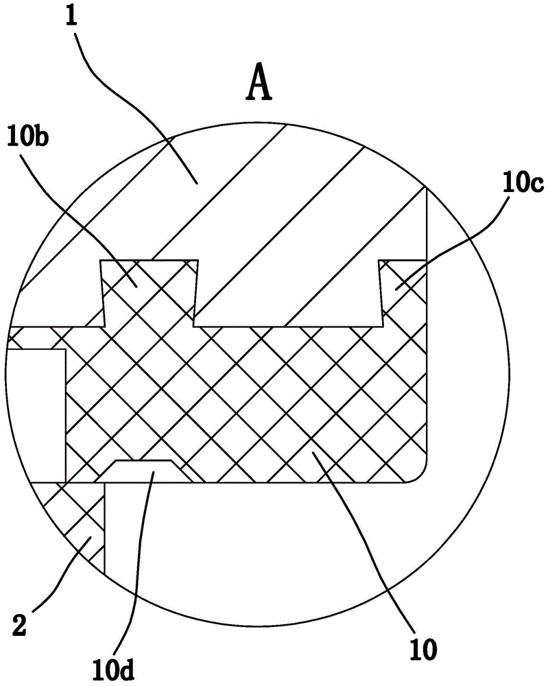
[0044] Among them, the valve seat 1, the guide sleeve 3, and the lift limiter 4 are sequentially sleeved on the bolt 6, the valve plate 2 is sleeved on the guide sleeve 3 and is located between the valve seat 1 and the lift limiter 4, and the guide sleeve 3 plays a guiding role on the valve plate 2. The lift limiter 4 and the bolt 6 are fixedly connected. One end of the spring 5 is fixed on the lift limiter 4, and the other end is on the back of the valve plate 2. A lock nut 7 and a lock nut 7 are arranged above the valve seat 1. It is screwed on the bolt 6 and abuts against the outer end of the valve seat 1. An anti-loosening pin 8 is provided between the bolt 6 and the lift limiter 4 for positioning, the lift limiter 4 and the valve seat 1 are positioned by ...
Embodiment 2
[0056] The structure and principle of the second embodiment are basically the same as those of the first embodiment, and the difference lies in: Image 6 with Figure 7 As shown, the compressor air valve is a closed air valve, in which the edge of the first plastic gasket 10 and the edge of the second plastic gasket 11 abut together, and the inner end surface of the lift limiter 4 has an arc Shaped limiting groove 4d, the limiting groove 4d and the bolt 6 are arranged coaxially, the limiting slot 4d includes a larger slot width limiting section 4d1 and a smaller slot width connecting section 4d2, the connecting section 4d2 is located in the limiting section 4d1 Between the second plastic gasket 11 and the second plastic gasket 11, a limiting head 11d matching the limiting groove 4d is correspondingly provided on the second plastic gasket 11, and the limiting head 11d is embedded in the limiting groove 4d. By setting the limit head 11d to be embedded in the limit slot 4d, the as...
Embodiment 3
[0058] The structure and principle of the third embodiment are basically the same as those of the first embodiment. The difference is that the connecting structure includes a connecting hole on the inner end surface of the valve seat 1 and a connecting column on the first plastic gasket 10 that matches the connecting hole. There are at least two connecting holes and they are evenly distributed along the circumferential direction. The connecting holes are tapered and the diameter of the connecting holes gradually decreases toward the first plastic gasket 10. The number of connecting posts is the same as the connecting holes and their positions correspond to each other. Embedded in the connecting hole, the tapered connecting column is embedded in the tapered connecting hole, which can also limit the downward movement of the first plastic gasket 10, so that the first plastic gasket 10 and the valve seat 1 Securely and stably fix them together, which improves the service life of the...
PUM
 Abstract
Description
Claims
Application Information
 - R&D
- Intellectual Property
- Life Sciences
- Materials
- Tech Scout
- Unparalleled Data Quality
- Higher Quality Content
- 60% Fewer Hallucinations
Browse by: Latest US Patents, China's latest patents, Technical Efficacy Thesaurus, Application Domain, Technology Topic, Popular Technical Reports.
© 2025 PatSnap. All rights reserved.Legal|Privacy policy|Modern Slavery Act Transparency Statement|Sitemap|About US| Contact US: help@patsnap.com


