Copying machine with fan

A copier and a fan-equipped technology, applied in the fields of electrical recording technology using charge graphics, equipment using electrical recording technology using charge graphics, and electrical recording technology, can solve the problem of no heat dissipation and heat removal in copiers, and achieve simple structure, Strong usability effect

Inactive Publication Date: 2015-04-15
WIIMEDIA SOFTWARE
View PDF0 Cites 0 Cited by
  • Summary
  • Abstract
  • Description
  • Claims
  • Application Information

AI Technical Summary

Problems solved by technology

[0003] The purpose of the present invention is to overcome the problem that the copier in the prior art can not freely reverse the direction to dissipate heat and remove heat

Method used


Image

  • Copying machine with fan
  • Copying machine with fan
  • Copying machine with fan

Examples


Embodiment 1

[0015] Embodiment 1: in combination with figure 1 , 2 describe.

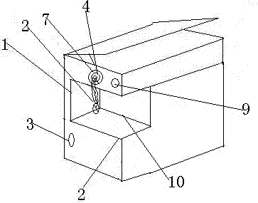
[0016] A copying machine with a fan, comprising a casing 1 and a power supply 3 placed in the casing 1, a paper outlet 10 above the casing 1 is installed detachably connected to the casing 1 and electrically connected to the power supply 3 fan2.

[0017] The scheme has been realized, so that the copier has the functions of heat dissipation and blowing.

Embodiment 2

[0018] Embodiment 2, in conjunction with attached figure 1 , 2 , 3 description.

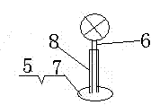
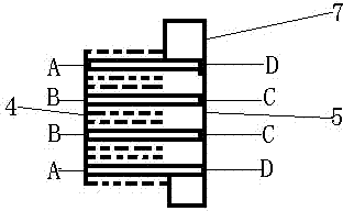
[0019] Based on the first embodiment, the fan 2 includes a fan head, a fan neck 6 and a fan seat 7 from top to bottom. The left side of the housing 1 is inwardly formed with an annular socket 4 connected to the power supply 3 ; Fan neck 6 has universal pipe 8. The fan 2 has a gear switch 9.

[0020] The preferred universal tube, annular interface, and gear switch in this scheme can make the fan and the back of the housing detachably fixedly connected. When not in use, it can be rotated clockwise or counterclockwise. When in use, the angle of the fan head can be adjusted arbitrarily And a certain height, and can adjust the wind speed.


PUM


Abstract

The invention belongs to the technical field of electric appliance, and provides a copying machine with a fan. The copying machine comprises a shell and a power supply arranged in the shell, and the back side of the shell is provided with the fan which is detachably connected with the shell and connected with the power supply. The office copying machine has heat-radiation function, solves the problems that discharged paper is overheated and easy to deform when a copy shop performs copying in batch for a long time, can be used as a fan when necessary, and is simple in structure and high in practicability.

Description

technical field [0001] The invention belongs to the technical field of electrical appliances, and in particular relates to a copier with a fan. Background technique [0002] Most existing office copiers have single functions and cannot meet the needs of modern offices. In professional printing shops, printers have to work repeatedly for a long time every day, and people have to follow suit. The paper produced by printers after long hours of work is It is easy to deform when it is hot, especially in summer. Most of the existing ones are placed flat or blown by an independent fan, which is costly and inconvenient to use. Contents of the invention [0003] The purpose of the present invention is to overcome the problem that the copier in the prior art can not freely reverse the direction to dissipate heat and remove heat. [0004] To this end, the present invention provides a copier with a fan, which includes a casing and a power supply placed in the casing, above the paper...

Claims


Application Information

Patent Timeline
Patent Type & Authority Applications(China)
IPC IPC(8): G03G15/00G03G21/20
CPCG03G21/20
Inventor 张春江
Owner WIIMEDIA SOFTWARE
Why Eureka
Try Eureka