
Antenna, method for manufacturing antenna, and mobile terminal

A technology of a mobile terminal and a manufacturing method, applied in the field of communication, can solve problems such as damage, deviation from users, etc.

Active Publication Date: 2015-04-15
BEIJING ERENEBEN INFORMATION TECH
View PDF4 Cites 4 Cited by
  • Summary
  • Abstract
  • Description
  • Claims
  • Application Information

AI Technical Summary

Problems solved by technology

[0004] However, there are two problems in the existing antennas: 1. How to make the electromagnetic radiation local absorption ratio (Specific Absorbing Ratio, SAR) deviate from the user, so as not to cause damage to the human body

Method used


Image

  • Antenna, method for manufacturing antenna, and mobile terminal
  • Antenna, method for manufacturing antenna, and mobile terminal
  • Antenna, method for manufacturing antenna, and mobile terminal

Examples


Embodiment Construction

[0038] The following will be described in conjunction with the accompanying drawings and specific embodiments.

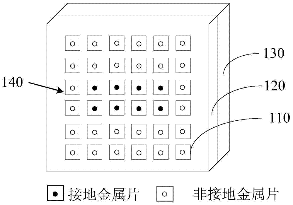
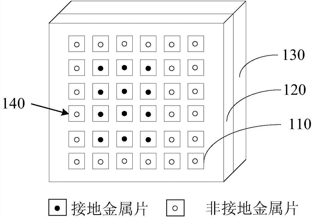
[0039] see figure 2 as well as image 3 , the present invention provides an antenna, including a plurality of metal sheets 110, a ground layer 130 and a switching device (not shown in the figure).

[0040] The plurality of metal sheets 110 and the ground layer 130 are both connected to the switching device. The switching device has at least the first and second frequency band configuration modes. When the switching device is in the first frequency band configuration mode, the switching device makes the first number of metal sheets 110 communicate with the ground layer 130, wherein the first number of metal sheets 110 also has a first distribution, the first number is the number of metal sheets that make the antenna work in the first frequency band, such as figure 2 As shown; when the switching device is in the second frequency band configuration mode, the switc...


PUM


Abstract

The invention discloses an antenna, a method for manufacturing the antenna, and a mobile terminal. The antenna comprises a plurality of metal sheets, a ground layer, and a switching element. The switching element comprises at least a first frequency band configuration mode and a second frequency band configuration mode. When the switching element is in the first frequency band configuration mode, the switching element makes the metal sheets in first number communicated with the ground layer. The metal sheets in first number are distributed in first distribution. When the switching element is in the second frequency band configuration mode, the switching element makes the metal sheets in second number communicated with the ground layer. The metal sheets in second number are distributed in second distribution. Through the above method, the antenna can realize reception of multiband antenna, and the antenna in each frequency band conforms to detection standard of SAR.

Description

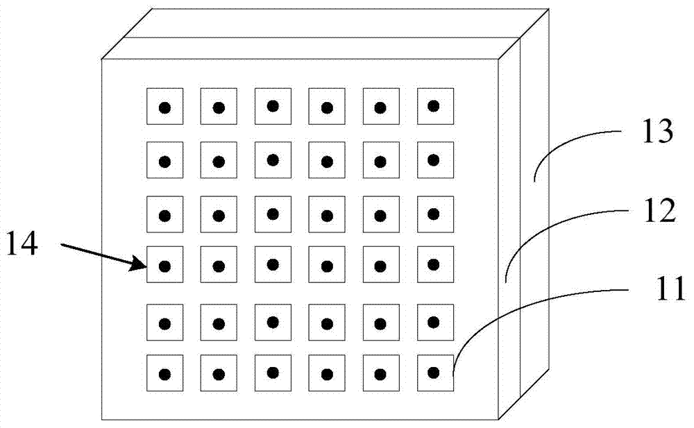
technical field [0001] The present invention relates to the technical field of communications, in particular to an antenna, a manufacturing method of the antenna and a mobile terminal. Background technique [0002] The antenna is an important part of the mobile terminal, and the mobile terminal receives or transmits data through the antenna. [0003] The prior art provides an antenna with an Electromagnetic Band-Gap (EBG) structure, such as figure 1 As shown, the antenna includes a plurality of metal sheets 11 , a dielectric plate 12 and a ground layer 13 arranged in an array. The dielectric board 12 is provided with via holes 14 corresponding in quantity and position to the metal sheets 11 , and the metal sheets 11 are connected to the ground layer 13 through the via holes 11 . The receiving frequency band of the antenna is related to the number of the metal pieces 110 , so the antenna in the prior art can transmit and receive wireless signals of one frequency band after ...

Claims


Application Information

Patent Timeline
IPC IPC(8): H01Q1/24H01Q1/38H01Q5/00H01Q1/50
Inventor 刘锋龚道哲周佳杜国楹
Owner BEIJING ERENEBEN INFORMATION TECH
Learn More