Winder for binding cable binding wire

A cable winder and wire binding technology, which is applied in the direction of connecting/terminating cable equipment, etc., can solve the problems of inflexible finger movement, loose and tight wire binding, gaps, and short distances, so as to save manual operation intensity and tie The coil is strong and tight, and the effect of saving operation time

Active Publication Date: 2015-04-15
STATE GRID CORP OF CHINA +1
View PDF5 Cites 4 Cited by
  • Summary
  • Abstract
  • Description
  • Claims
  • Application Information

AI Technical Summary

Problems solved by technology

When wiring, the insulation layer on one end of the main cable is stripped off, and the cable core of the other cable is connected to the conductive core of the main cable. Wrap the two cables tightly to form a firm joint. During construction, the construction personnel wear insulating gloves, use pliers and other tools with their hands, and use binding wires to wrap the wires at the cable joints to form a circle. The distance is short, and the live operation is unsafe; because the fingers are not flexible when wearing insulating gloves to wrap the wiring, the binding wire is not tightly wound and there are gaps; wearing gloves and using pliers for a long time, the hands will feel sore; due to long-term operation, Uneven force, inaccurate contact surface
The double-slot line connection is to put two wire ends in the two slots of a metal clip with two slots, and then use the metal clip to clamp the two wire ends to power on. Actually, the clip is easy to fall off

Method used


Image

  • Winder for binding cable binding wire
  • Winder for binding cable binding wire
  • Winder for binding cable binding wire

Examples


Embodiment Construction

[0026] Below in conjunction with accompanying drawing, the present invention is described in further detail:

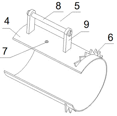
[0027] Winders for bundling cable ties such as Figure 4 As shown, the wire winder includes a ratchet part 2 and a pawl part 3, and the ratchet part 2 and the pawl part 3 are arranged correspondingly. like figure 1 As shown, the ratchet part 2 includes a sleeve 4 with a notch on one side. A support 5 is arranged on the outer surface of the sleeve 4. The support 5 is used to set up the binding shaft 1. The wall of the sleeve 4 corresponds to the bottom of the support 5. A circular hole 7 for passing the binding wire wound on the binding shaft 1 is provided at the corresponding position, and the bracket 5 is located at a position close to the side opening of the sleeve 4 . The bracket 5 includes two opposite side plates 9 and a cross arm 8 , the cross arm 8 is a screw with a nut, and the cross arm 8 is connected between the two side plates 9 . The outer circumference...


PUM


Abstract

The invention discloses a winder for binding a cable binding wire. The winder is applicable to winding of a cable joint through a power system. The winder comprises a ratchet part and a pawl part corresponding to the ratchet part, wherein the ratchet part comprises a sleeve with a side opening; ratchet teeth are arranged on the outer circumference of the sleeve and are correspondingly sleeved by the pawl part; the pawl part comprises a circular-arc-shaped pawl body which is provided with a long handle and a side opening corresponding to the sleeve and can span over the side opening of the sleeve; at least two pawls matched with the ratchet teeth are arranged on the pawl body. By utilizing the principle of interaction between the ratchet and the pawls, the ratchet can move in a single direction by virtue of the reciprocating motion of the ratchet teeth; when the pawl part is rotated clockwise, the pawls drive the ratchet teeth to move together, and the ratchet teeth drive a wire binding shaft on the sleeve to move; when the pawl part is rotated anticlockwise, the ratchet teeth is not rotated along with the pawl part, and the aim of winding a binding wire of a binding wire shaft on two wire joints can be achieved by moving an insulating handle connected with the pawl part up and down.

Description

technical field [0001] The invention relates to a cable winder, in particular to a cable winder used in a charged state. Background technique [0002] In the power system, it is often necessary to connect two cable ends. In the charged state, the connection methods of the two cable ends include winding connection and double-slot line connection. When wiring, the insulation layer on one end of the main cable is stripped off, and the cable core of the other cable is connected to the conductive core of the main cable. Wrap the two cables tightly to form a firm joint. During construction, the construction personnel wear insulating gloves, use pliers and other tools with their hands, and use binding wires to wrap the wires at the cable joints to form a circle. The distance is short, and the live operation is unsafe; because the fingers are not flexible when wearing insulating gloves to wrap the wiring, the binding wire is not tightly wound and there are gaps; wearing gloves and ...

Claims


Application Information

Patent Timeline
Patent Type & Authority Applications(China)
IPC IPC(8): H02G1/14
Inventor 白胜民高坤生刘剑锋魏华
Owner STATE GRID CORP OF CHINA
Why Eureka
Try Eureka