
yarn feeder

A yarn feeder and yarn feeding wheel technology, applied in textile and papermaking, knitting, weft knitting and other directions, can solve the problems of complex production and so on

Active Publication Date: 2017-02-15
MEMMINGER IRO GMBH
View PDF9 Cites 0 Cited by
  • Summary
  • Abstract
  • Description
  • Claims
  • Application Information

AI Technical Summary

Problems solved by technology

The manufacture of such a carrier with aligned bearing seats for support requires complex fabrication

Method used


Image

  • yarn feeder
  • yarn feeder
  • yarn feeder

Examples


Embodiment Construction

[0074] first example

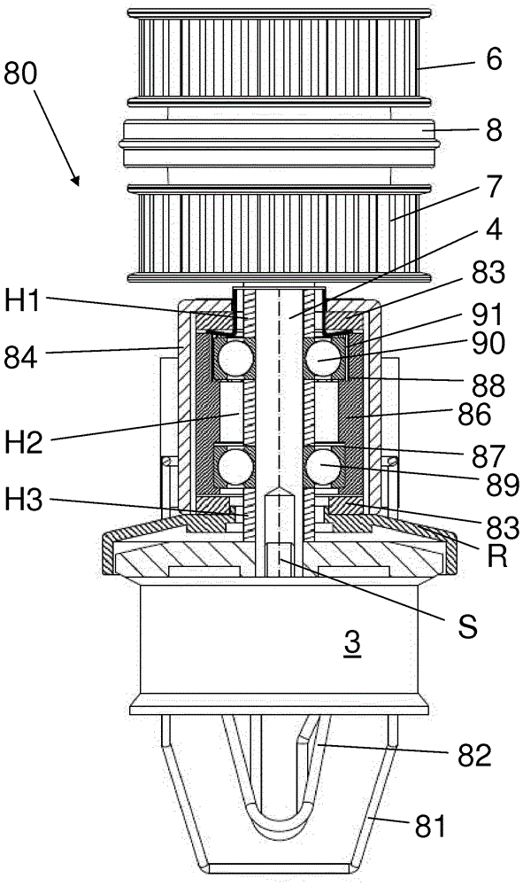
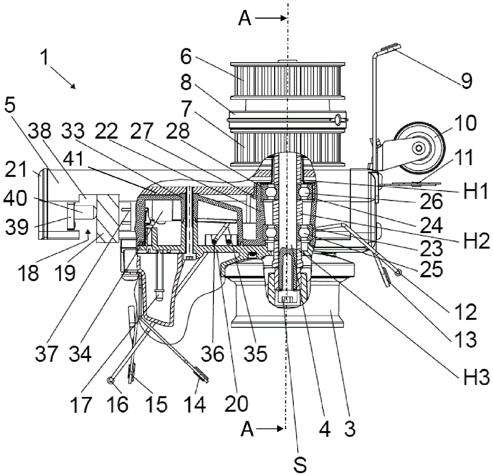
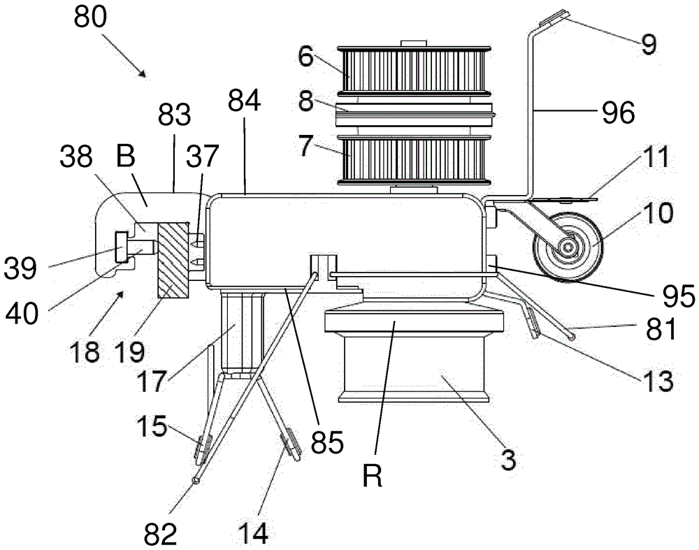
[0075] Figures 1 to 3 A first example of a yarn feeder 1 according to the invention is shown for delivering yarn 2 to a textile machine, in particular a circular weaving machine. The yarn feeder 1 has a yarn feed wheel 3 and a drive shaft 4 . The yarn feed wheel 3 is fixed on the textile machine in such a way that the drive shaft 4 (that is to say its axis of rotation) extends vertically. The yarn feeding wheel 3 is arranged at the drive shaft 4 .

[0076] The yarn feeder 1 comprises a carrier 5 for supporting the drive shaft 4 and for fixing the yarn feeder 1 at the textile machine.

[0077] The yarn feeding wheel 3 is fixed on the lower end of the drive shaft 4 with a bolt S.

[0078] At the upper end of the drive shaft 4 at least one (preferably a plurality) of belt pulleys 6 , 7 is arranged. Between the pulleys 6 , 7 there is at least one coupling disc 8 or other coupling means. The belt pulleys 6 , 7 are rotatably mounted on the drive shaft 4...


PUM


Abstract

The invention relates to a thread delivery device (1, 50, 50', 80), which is provided with a thread delivery wheel (3), a drive shaft (4), on which the thread delivery wheel (3) is arranged, a carrier (5, 51, 83, 100) having at least one bearing retainer (22, 59, 86), and at least one rolling-element bearing (25, 26; 62, 63; 89, 90; 103, 104) for supporting the drive shaft (4). The bearing retainer has at least one undivided bearing seat (23, 24), in which the rolling-element bearing (25, 26) is arranged. The carrier (5, 51, 83, 100) is formed from at least one segment of a continuous profiled element.

Description

technical field [0001] The invention relates to a yarn feeder for feeding yarn to a textile machine, in particular a circular loom, with a feed wheel, a drive shaft and a carrier, wherein the feed wheel is arranged at the drive shaft, and the carrier has a At least one support bracket supporting the drive shaft. Background technique [0002] Such a yarn feeder is known from document EP 1 194 621 B1. The carrier of the yarn feeder is constructed from plastic as a two-part housing. Arranged in each housing part is an undivided bearing seat with a receptacle for the rolling bearing which is open axially to one side. In the gap between the rolling bearing and the bearing seat there is a pressing element, which is formed from an elastomer. [0003] The two housing parts consisting of plastic have to be produced in a complex manner. In order to fulfill the carrier function at the same time, very thick wall regions are required in some cases. In order to compensate for manufac...

Claims


Application Information

Patent Timeline
Patent Type & Authority Patents(China)
IPC IPC(8): D04B15/48
CPCD04B15/48D04B15/482
Inventor U.M.格罗施A.霍瓦尔特C.韦尔纳
Owner MEMMINGER IRO GMBH
Learn More