
Controller assembly and cab for operation machinery

A technology for operating machinery and controllers, which is applied in the field of controller assemblies and cabs for operating machinery, which can solve the problems of reduced space for configuring controllers, difficulties in equipment assembly, and repairs, and achieve the effect of easy repairs

Inactive Publication Date: 2015-04-15
KOMATSU LTD
View PDF11 Cites 2 Cited by
  • Summary
  • Abstract
  • Description
  • Claims
  • Application Information

AI Technical Summary

Problems solved by technology

Therefore, there is a problem that the space for arranging the controller is reduced, and the assembly and repair of the equipment become difficult.

Method used


Image

  • Controller assembly and cab for operation machinery
  • Controller assembly and cab for operation machinery
  • Controller assembly and cab for operation machinery

Examples


Embodiment Construction

[0038] Hereinafter, embodiments of the present invention will be described based on the drawings.

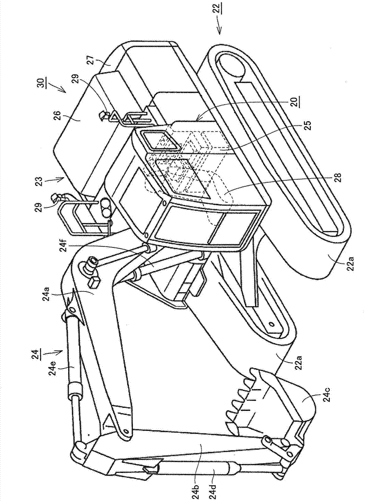
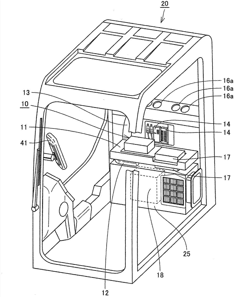
[0039] First, the configuration of a work machine according to an embodiment of the present invention will be described. Hereinafter, as an example of a work machine to which the idea of ​​the present invention can be applied, use figure 1 and figure 2 A hydraulic excavator and a cab used for the hydraulic excavator will now be described. It should be noted that the present invention can also be applied to work machines having a cab, such as bulldozers and wheel loaders, in addition to hydraulic excavators.

[0040] figure 1 It is a perspective view schematically showing the structure of a hydraulic excavator according to an embodiment of the present invention. figure 2 yes means figure 1 Partial enlarged perspective view of the cab of the hydraulic excavator.

[0041] Such as figure 1 As shown, the hydraulic excavator 30 mainly includes a lower traveling body 22 , an u...


PUM


Abstract

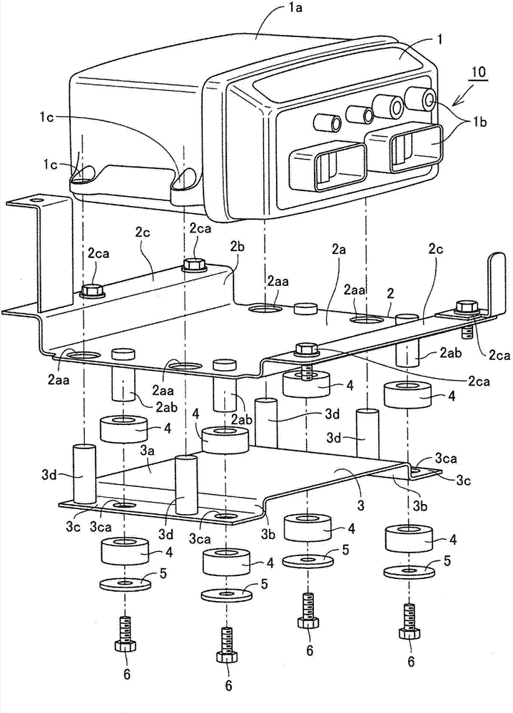
A connection plate (3) is arranged below a mounting member (2). A damping member (4) is assembled between the mounting member (2) and the connection plate (3). A first controller main body (1) is arranged above the mounting member (2). A connection member (3d) enables the connection plate (3) to be connected with the first controller main body (1).

Description

technical field [0001] The present invention relates to a controller assembly and a cab for a working machine. Background technique [0002] In recent years, more machine controllers have been mounted on work machines than ever before as they become more functional. [0003] The structure and arrangement of such a machine controller are disclosed in Japanese Patent No. 5538575, for example. In this publication, a placement plate is disposed on the bottom surface of a U-shaped bracket in side view with a vibration damping member interposed therebetween, and a machine controller is disposed on the placement plate. Since the vibration is attenuated by the vibration damping member between the bracket and the mounting plate, the controller arranged on the mounting plate is protected from the influence of the acceleration of the vehicle. [0004] prior art literature [0005] patent documents [0006] Patent Document 1: Japanese Patent No. 5538575 Contents of the invention ...

Claims


Application Information

Patent Timeline
Patent Type & Authority Applications(China)
IPC IPC(8): E02F9/20E02F9/16
CPCB60R11/0264B60R2011/0052E02F9/0858E02F9/163B60H1/00378B60Y2200/412E02F9/16E02F9/2004E02F9/2025H05K5/0217
Inventor 长野正裕本间义朗塚本大介田中宏章菊间智子
Owner KOMATSU LTD
Learn More