screw pump

A screw pump, screw technology, applied in the direction of pumps, pump components, rotary piston pumps, etc., can solve limited and other problems, achieve uniform mass distribution, avoid downtime, and increase the delivery volume

Active Publication Date: 2016-12-07
STERLING IND CONSULT GMBH
View PDF6 Cites 0 Cited by
  • Summary
  • Abstract
  • Description
  • Claims
  • Application Information

AI Technical Summary

Problems solved by technology

However, the delivery capacity, i.e. the ability to expel a large volume of gas from a space in a short period of time, is limited compared to other pumps

Method used


Image

  • screw pump
  • screw pump
  • screw pump

Examples


Embodiment Construction

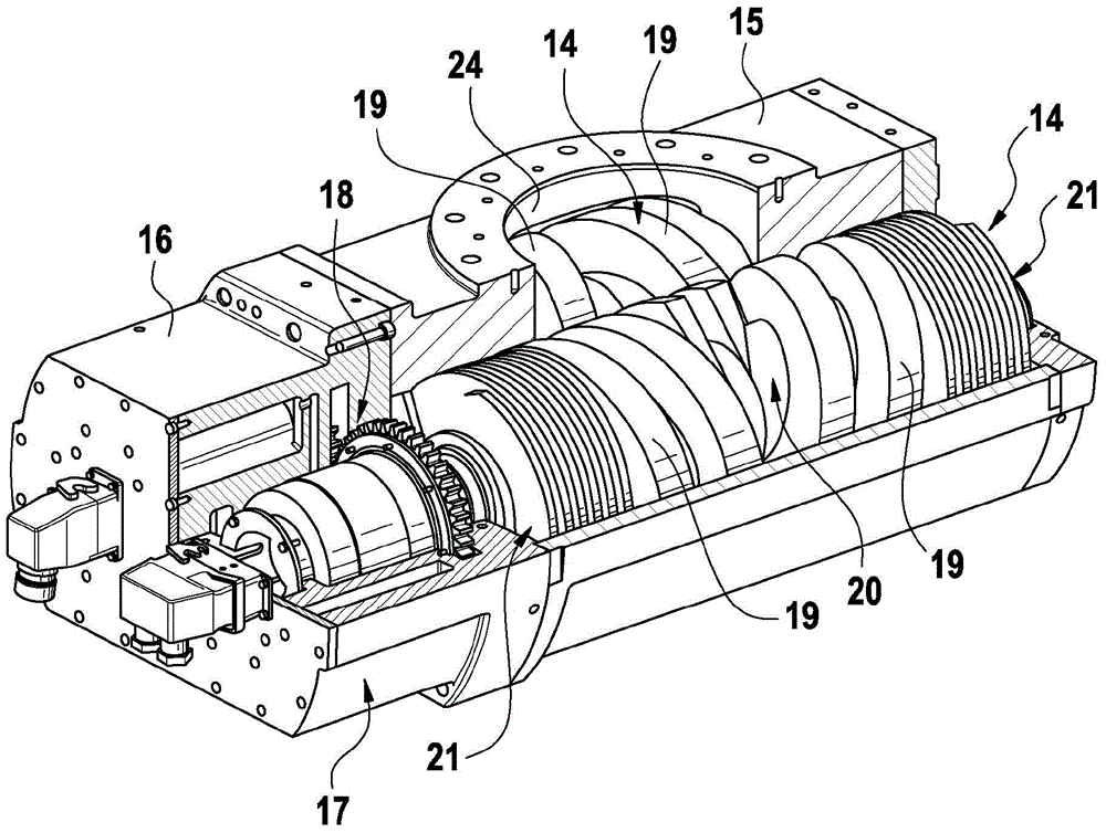
[0036] figure 1 In this case, the pump of the present invention comprises two screw rods 14 housed in a pump housing 15 . Due to the not fully shown pump housing 15 , one of the screw rods 14 can be seen in full length, while the other screw rod 14 is substantially covered by the pump housing 15 . The two screws 14 engage each other, which means that the threaded protrusions of one screw 14 engage into the recesses between the two threaded protrusions of the other screw 14 .

[0037] The pump comprises a control and drive unit 16 in which an electrically controlled drive motor 17 is provided for each screw 14 . The electronic controller of the drive motor 17 is arranged so that the two screws 14 run perfectly synchronously with respect to each other, and the thread protrusions of the screws 14 do not touch. In addition, each screw 14 is equipped with a gear 18 as a safety measure against damage to the screws 14 . The gears 18 engage each other, causing a positive coupling o...


PUM


Abstract

The invention relates to a progressive cavity pump with two screws (14), in which each screw (14) has a first thread (19) and a second thread (19). Each of the threads (19) extends from the suction side (20) to the output side (21), and the two threads (19) engage with each other so that the threads (19) are divided into a plurality of working chambers, the working The volume of the cavity decreases from said suction side (20) to said delivery side (21). According to the invention, said thread (19) has two thread turns. Furthermore, the invention relates to a screw for a pump of this type. Due to the uniform distribution of the mass of the two turns of the thread, the pump can be operated at high rotational speeds, so that the delivery capacity of the pump is increased.

Description

technical field [0001] The invention relates to a screw pump with two screws. Each screw is equipped with a first flight and a second flight, which in each case extend from the suction side to the delivery side. The threads engage each other, with the result that the threads are divided into working chambers. In each case, the volume of the working chamber decreases from the suction side to the discharge side. Furthermore, the invention relates to a screw for this type of pump. Background technique [0002] This type of screw pump can be used to create a vacuum. The space to be evacuated is connected to the suction side of the pump, with the result that the pump can draw gas from said space. The gas is compressed in the pump and is delivered again at a higher pressure on the delivery side. [0003] The screw pump has a set of favorable characteristics and thus is used in a wide range. However, delivery capacity, ie the ability to expel large volumes of gas from a space...

Claims


Application Information

Patent Timeline
Patent Type & Authority Patents(China)
IPC IPC(8): F04C18/08F04C18/16
CPCF04C18/084F04C18/086F04C18/16F04C2220/12F04C2240/402F04C2230/605F04C23/001F04C29/12F04C2250/101F04C23/003
Inventor 海纳·科斯特耶格·泰敏
Owner STERLING IND CONSULT GMBH
Why Eureka
Try Eureka