Electronic mechanical brake device for railway vehicle

An electromechanical braking and rail vehicle technology, applied in the direction of braking transmissions, brakes, vehicle components, etc., can solve the problems of large brake size and low output efficiency, reduce volume, reduce production costs, and ensure braking force output effect

Pending Publication Date: 2021-12-21
SHANXI GUOLI INFORMATION TECH
View PDF0 Cites 0 Cited by
  • Summary
  • Abstract
  • Description
  • Claims
  • Application Information

AI Technical Summary

Problems solved by technology

[0005] In order to solve the technical problems of large size and low output efficiency of existing brakes, the invention provides an electromechanical brake device for rail vehicles

Method used


Image

  • Electronic mechanical brake device for railway vehicle
  • Electronic mechanical brake device for railway vehicle
  • Electronic mechanical brake device for railway vehicle

Examples


Embodiment 1

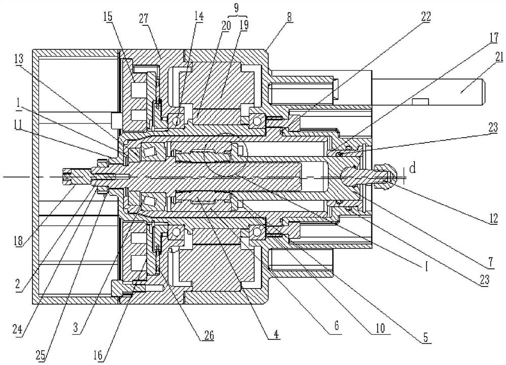
[0071] Such as figure 1 and figure 2 As shown, the present embodiment is an electromechanical brake device for rail vehicles, including a drive motor 9, a fixed sleeve 1, a planetary roller mechanism, a front housing 8, an output shaft 7 and a clutch lock mechanism.

[0072] The front housing 8 is connected to the front end of the fixed sleeve 1 to form a cavity, and an O-ring 22 is arranged at the joint between the front housing 8 and the fixed sleeve 1; the cavity is partially filled with lubricating oil or grease.

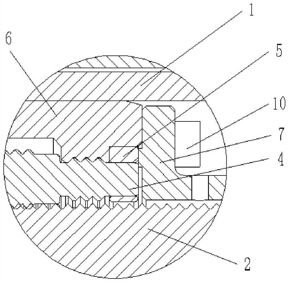
[0073] Such as image 3 and Figure 4 As shown, the planetary roller mechanism includes an input shaft 2, two positioning rings 5, a roller frame 6 and N planetary rollers 4, N is an integer greater than 2, and N in this embodiment is 6; the input shaft 2 is arranged in the cavity and Coaxial with the fixed sleeve 1, a cone bearing 3 is provided between the output shaft 7 and the inner wall of the fixed sleeve 1, and the cone bearing 3 is located at the rear...

Embodiment 2

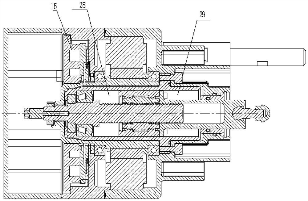
[0085] The difference from Embodiment 1 is that the driving motor 9 is a double motor, such as Figure 5 As shown, in this embodiment, the dual motors adopt coaxial dual stators and single rotor to realize design redundancy and improve the reliability of the overall equipment. In other embodiments, the double motors may also adopt a coaxial double stator and double rotor structure.

Embodiment 3

[0087] The difference from the first embodiment is that the front end of the input shaft 2 is provided with a plurality of first annular grooves at equal intervals, and the middle part of the planetary roller 4 is provided with an external thread matching the first annular grooves.


PUM


Abstract

The invention provides an electronic mechanical brake device for a railway vehicle, and solves the problem that an existing brake is large in size and low in output efficiency. The device comprises a driving motor, a fixing sleeve, a planetary roller mechanism, a front shell, an output shaft and a clutch lock locking mechanism, wherein the front shell is connected with the fixing sleeve to form a cavity; the planetary roller mechanism comprises an input shaft, two positioning rings, a roller frame and a plurality of planetary rollers; the input shaft is arranged in the cavity, the rear end extends out of the cavity, and the front end is provided with an external thread or an annular groove; the roller frame is arranged between the fixing sleeve and the input shaft; the two positioning rings are axially limited at the two ends of the roller frame; the plurality of planetary rollers are arranged on the two positioning rings; the output shaft is arranged in the cavity, and the front end extends out of the cavity; the output shaft can realize non-rotating forward and backward movement in the axial direction; the driving motor is used for driving the input shaft to rotate and driving the N planetary rollers to rotate and revolve, and the planetary rollers drive the output shaft to move front and back in the axial direction of the input shaft; and the clutch lock locking mechanism is used for separating and locking the input shaft.

Description

technical field [0001] The invention relates to electromechanical brake technology, in particular to an electromechanical brake device for rail vehicles. Background technique [0002] With the rapid development of automobile technology, the continuous increase of traffic flow density and the gradual increase of vehicle speed, the requirements for the safety and reliability of automobiles are getting higher and higher. Whether the automobile braking system can quickly and effectively realize the driver's braking intention in real time, become a key issue affecting road traffic safety. [0003] Due to the complexity of the traditional hydraulic braking system, the braking force needs to pass through the vacuum booster, hydraulic pipeline, etc., resulting in slow response, large volume, difficult layout and assembly on the vehicle, complex electronic control system, high manufacturing and maintenance costs, etc. Many flaws. The electromechanical brake system (EMB) not only ov...

Claims


Application Information

Patent Timeline
IPC IPC(8): B60T13/74
CPCB60T13/746
Inventor 潘亚敏杨铜新
Owner SHANXI GUOLI INFORMATION TECH
Why Eureka
Try Eureka