High-low temperature damp-hot test box

A damp heat test, high and low temperature technology, applied to laboratory appliances, heating or cooling equipment, shells or chambers, etc., can solve the problems of procurement funds, space, energy waste, difficult to achieve thermal load capacity, etc., to achieve control equipment Cost and equipment volume, effect of volume reduction

Active Publication Date: 2015-04-22
沈阳华测检测技术有限公司
View PDF5 Cites 6 Cited by
  • Summary
  • Abstract
  • Description
  • Claims
  • Application Information

AI Technical Summary

Problems solved by technology

For tests other than high humidity, such as dry heat temperature test and low humidity test, if it is necessary to increase the thermal load capacity, without increasing the volume of the test chamber, it can be solved by increasing the cooling capacity, that is, it is necessary to configure a large cooling capacity Refrigeration unit; high humidity test, without increasing the volume of the test chamber, it is difficult to increase its thermal load capacity by traditional methods of increasing cooling capacity
In reality, some test samples, such as LED lamps, need to be energized under high-humidity conditions. At this time, the LED lamps release the heat load to the test area by emitting light. The heat load released in the form of luminescence will be relatively large. To meet this condition, you need to purchase a test chamber that is much larger than the size of the test sample. In addition, you must also configure a larger one that matches this. Refrigeration units, heaters, humidifiers, etc., resulting in unnecessary waste of procurement funds, space, energy, etc.

Method used


Image

  • High-low temperature damp-hot test box
  • High-low temperature damp-hot test box
  • High-low temperature damp-hot test box

Examples


Embodiment Construction

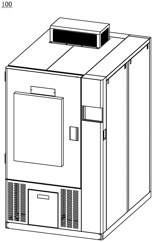
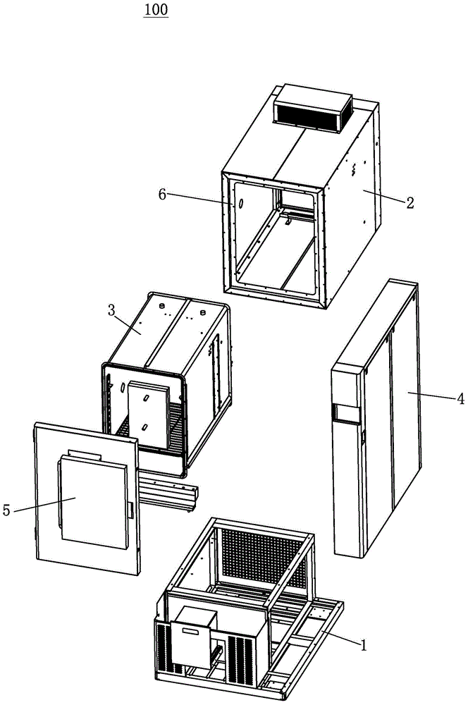
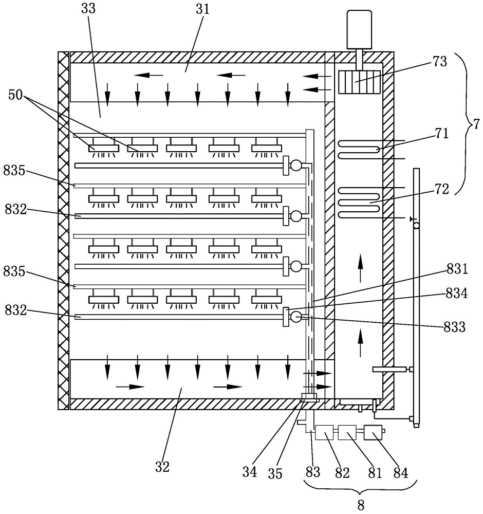
[0023] Now refer to the attached figure 1 To describe embodiments of the present invention, like reference numerals in the drawings represent similar elements. As mentioned above, such as Figure 1-5 As shown, the high and low temperature damp heat test chamber 100 disclosed in the embodiment of the present invention includes: a bracket 1, an outer box body 2, an inner box body 3, a side box body 4, a box door 5 and a processing device 7. The inner box 3 is nested inside the outer box 2, the processing device 7 is arranged in the side box 4, the side box 4 is attached to one side of the outer box 2, and the outer box An insulating layer 6 is provided between the box body 2 and the inner box body 3, and a channel is provided between the side box body 4, the outer box body 2 and the inner box body 3, and the channel is as Figure 4 As shown, it is arranged on the opposite side walls of the inner box body 3 and the side box body 4, and holes are opened at the upper and lower en...


PUM


Abstract

The invention discloses a high-low temperature damp-hot test box comprising a bracket, an outer box body, an inner box body, a side box body, a box door and a processing device; the inner box body is internally provided with an air-out channel and an air return channel, and a test area is formed between the air-out channel and the air return channel; the processing device comprises a heating device, a first refrigerating device, and a draught fan for making gas cycle among the air-out channel, the test area and the air return channel; the draught fan cooperates with the heating device or the first refrigerating device to generate hot airflow or cold airflow; the test box also comprises an ultrasonic refrigerating humidifying device; the ultrasonic refrigerating humidifying device comprises a second refrigerating device, ultrasonic water mist generators and a water mist conveying pipeline; room-temperature pure water is refrigerated by the second refrigerating device, ultrasonic water mists are produced by the ultrasonic water mist generators and go into the water mist conveying pipeline, water mist outlets are arranged on the water mist conveying pipeline, and to-be-tested objects are arranged to directly face the water mist outlets. The high-low temperature damp-hot test box can effectively control the cost and the equipment size, so as to avoid the waste of energy and places.

Description

technical field [0001] The invention relates to the field of environmental test equipment, in particular to a high and low temperature damp heat test chamber. Background technique [0002] Ordinary test chambers usually have relatively small thermal load capacity, especially under high humidity conditions. For tests other than high humidity, such as dry heat temperature test and low humidity test, if it is necessary to increase the thermal load capacity, without increasing the volume of the test chamber, it can be solved by increasing the cooling capacity, that is, it is necessary to configure a large cooling capacity Refrigeration unit; high humidity test, without increasing the volume of the test chamber, it is difficult to increase its thermal load capacity through the traditional method of increasing the cooling capacity. In reality, some test samples, such as LED lamps, need to be energized under high-humidity conditions. At this time, the LED lamps release the heat lo...

Claims


Application Information

Patent Timeline
Patent Type & Authority Applications(China)
IPC IPC(8): B01L1/00B01L7/00
Inventor 戴煦陈益思李波
Owner 沈阳华测检测技术有限公司
Why Eureka
Try Eureka