
Computer noiseless heat dissipation shell and heat dissipation method

A technology of heat dissipation shell and computer, which is applied in computing, instruments, electrical and digital data processing, etc., can solve the problems of computer influence, reduced computer service life, difficult computer heat dissipation, etc., to achieve good social and economic benefits, ensure normal use, Good cooling effect

Active Publication Date: 2020-04-10
HUNAN UNIV OF ARTS & SCI
View PDF6 Cites 0 Cited by
  • Summary
  • Abstract
  • Description
  • Claims
  • Application Information

AI Technical Summary

Problems solved by technology

[0002] With the development of society and the continuous advancement of computer science and technology, computers are gradually being used widely. However, when the computer mainframe is used for a long time, the internal components of the computer will generate a lot of heat. When the computer cannot be effectively dissipated, During the use of the computer, there will be bad problems such as freezing, black screen, etc., and even the service life of the computer will be greatly reduced.
[0003] At present, the heat dissipation of computers is often realized by using the airflow generated by the top-blown fan. This heat dissipation method is relatively limited, and it is difficult to dissipate heat for the computer as a whole. Moreover, the airflow generated is easy to bring dust into the computer and there is a problem of high noise, thus affecting the computer. impact, and the outer wall of the computer is supported by an ordinary metal hard sheet, and the metal hard sheet does not have a good heat dissipation effect

Method used


Image

  • Computer noiseless heat dissipation shell and heat dissipation method
  • Computer noiseless heat dissipation shell and heat dissipation method
  • Computer noiseless heat dissipation shell and heat dissipation method

Examples


Embodiment Construction

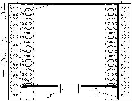
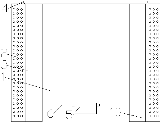
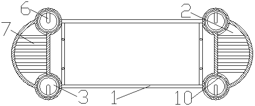
[0022] like figure 1 , 2 , 3, 4, and 5, a noiseless cooling case for a computer includes a computer case 1, the first heat dissipation case 2 is symmetrically arranged on both sides of the computer case 1, and the first heat dissipation case 2 The two sides of the two sides are symmetrically provided with the second heat dissipation shell 3, the first heat dissipation shell 2, the second heat dissipation shell 3 and the computer case 1 are integrally structured, and the first heat dissipation shell 2 communicates with the second heat dissipation shell 3 , a water cooling device is provided between the first cooling case 2 and the second cooling case 3, and a cooling device is provided between the second cooling case 3 and the computer case 1; the water cooling device includes a water injection port 4, and The nozzle 4 is welded and fixed on the top surface of the first heat dissipation housing 2, and the first heat dissipation housing 2 communicates with the water injection p...


PUM


Abstract

The invention relates to the technical field of computer hardware equipment. The invention relates to a computer, in particular to a computer noiseless heat dissipation shell and a heat dissipation method. Computer case, first heat dissipation shells are symmetrically arranged on the two sides of the computer case body. The computer case comprises a first heat dissipation shell, second heat dissipation shells are symmetrically arranged on the two sides of the first heat dissipation shell, the first heat dissipation shell, the second heat dissipation shells and the computer case body are of anintegrated structure, the first heat dissipation shell communicates with the second heat dissipation shells, a water cooling device is arranged between the first heat dissipation shell and the secondheat dissipation shells, and a heat dissipation device is arranged between the second heat dissipation shells and the computer case body; the computer noiseless heat dissipation shell and the heat dissipation method are high in heat dissipation efficiency, uniform in heat dissipation and low in heat dissipation noise, dust is prevented from being brought into a computer, and the computer noiselessheat dissipation shell and the heat dissipation method meet the requirements of users and are used for overcoming the defects in the prior art.

Description

technical field [0001] The invention relates to the technical field of computer hardware equipment, in particular to a computer noiseless heat dissipation casing and a heat dissipation method. Background technique [0002] With the development of society and the continuous advancement of computer science and technology, computers are gradually being used widely. However, when the computer mainframe is used for a long time, the internal components of the computer will generate a lot of heat. When the computer cannot be effectively dissipated, During the use of the computer, there will be bad problems such as freezing, black screen, etc., and even the service life of the computer will be greatly reduced. [0003] At present, the heat dissipation of computers is often realized by using the airflow generated by the top-blown fan. This heat dissipation method is relatively limited, and it is difficult to dissipate heat for the computer as a whole. Moreover, the airflow generated ...

Claims


Application Information

Patent Timeline
IPC IPC(8): G06F1/20G06F1/18
CPCG06F1/20G06F1/181
Inventor 陈潇潇王茂丰
Owner HUNAN UNIV OF ARTS & SCI
Learn More