
High temperature and high humidity test chamber

A high-temperature, high-humidity, test chamber technology, used in laboratory utensils, heating or cooling equipment, enclosures or chambers, etc., can solve the problems of procurement funds, space, energy waste, and difficulty in achieving heat load capacity, and achieve control The effect of equipment cost and equipment volume

Active Publication Date: 2016-03-16
上海华测品正检测技术有限公司
View PDF6 Cites 0 Cited by
  • Summary
  • Abstract
  • Description
  • Claims
  • Application Information

AI Technical Summary

Problems solved by technology

For tests other than high humidity, such as dry heat temperature test and low humidity test, if it is necessary to increase the thermal load capacity, without increasing the volume of the test chamber, it can be solved by increasing the cooling capacity, that is, it is necessary to configure a large cooling capacity Refrigeration unit; high humidity test, without increasing the volume of the test chamber, it is difficult to increase its thermal load capacity by traditional methods of increasing cooling capacity
In reality, some test samples, such as LED lamps, need to be energized under high-humidity conditions. At this time, the LED lamps release the heat load to the test area by emitting light. The heat load released in the form of luminescence will be relatively large. To meet this condition, you need to purchase a test chamber that is much larger than the size of the test sample. In addition, you must also configure a larger one that matches this. Refrigeration units, heaters, humidifiers, etc., resulting in unnecessary waste of procurement funds, space, energy, etc.

Method used


Image

  • High temperature and high humidity test chamber
  • High temperature and high humidity test chamber
  • High temperature and high humidity test chamber

Examples


Embodiment Construction

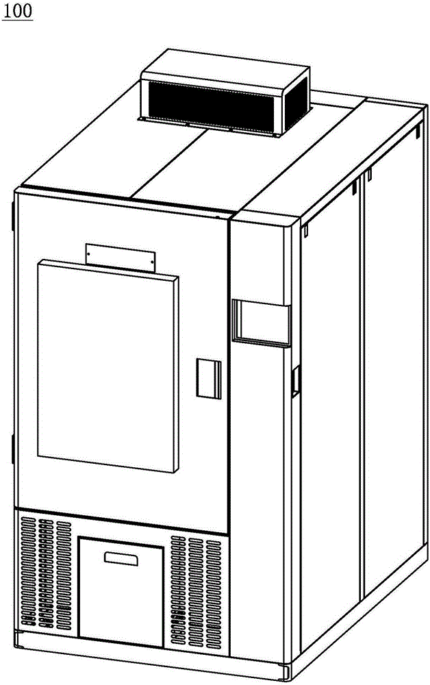
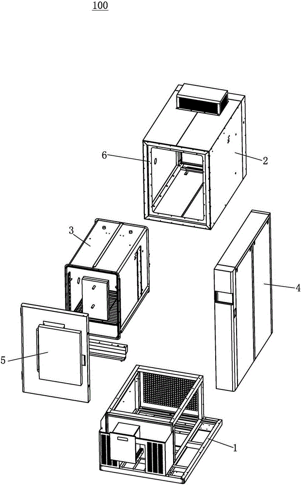
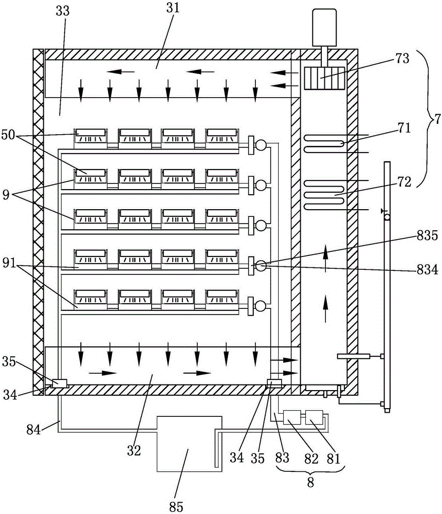
[0026] Now refer to the attached figure 1 To describe embodiments of the present invention, like reference numerals in the drawings represent similar elements. As mentioned above, such as Figure 1-3 As shown, the high-temperature and high-humidity test chamber 100 disclosed in the embodiment of the present invention includes: a bracket 1, an outer box 2, an inner box 3, a side box 4, a box door 5 and a processing device 7. The inner box 3 is nested inside the outer box 2, the processing device 7 is arranged in the side box 4, the side box 4 is attached to one side of the outer box 2, and the outer box An insulating layer 6 is provided between the box body 2 and the inner box body 3, and a passage is provided between the side box body 4, the outer box body 2 and the inner box body 3, and the side box body 4 and the inner box body The passage between the inner casing 3 is as Figure 5 As shown, the box door 5 is connected to the outer box body 2 and can seal the inner box bo...


PUM


Abstract

The invention discloses a high-temperature and high-humidity test box which comprises a support, an outer box body, an inner box body, a side box body, a box door and a processing device, wherein the processing device comprises a heating device, a first refrigeration device and a fan, and the fan is matched with the heating device or the first refrigeration device to produce hot air flow or cold air flow; the high-temperature and high-humidity test box further comprises a circulating cooling system and a plurality of fixture devices used for fixing tested articles; the circulating cooling system comprises a second refrigeration device, a water pump, a water delivery pipe and a water return pipe; the water pump is used for driving water in the water delivery pipe; the second refrigeration device is used for refrigerating water in the water delivery pipe; the fixture devices are provided with water channels, each water channel is provided with a water inlet and a drain port, the tested articles are fixed right above the water channels, the water inlets are connected with the water delivery pipe, the drain ports are connected with the water return pipe, and the water return pipe sequentially passes the second refrigeration device and the water pump and is connected to the water delivery pipe again so as to form the circulating cooling system. With the adoption of the high-temperature and high-humidity test box, the cost and the equipment size can be effectively controlled, and energy and field waste is avoided.

Description

technical field [0001] The invention relates to the field of environmental test equipment, in particular to a high-temperature and high-humidity test chamber. Background technique [0002] Ordinary test chambers usually have relatively small thermal load capacity, especially under high humidity conditions. For tests other than high humidity, such as dry heat temperature test and low humidity test, if it is necessary to increase the thermal load capacity, without increasing the volume of the test chamber, it can be solved by increasing the cooling capacity, that is, it is necessary to configure a large cooling capacity Refrigeration unit; high humidity test, without increasing the volume of the test chamber, it is difficult to increase its thermal load capacity through the traditional method of increasing the cooling capacity. In reality, some test samples, such as LED lamps, need to be energized under high-humidity conditions. At this time, the LED lamps release the heat lo...

Claims


Application Information

Patent Timeline
Patent Type & Authority Patents(China)
IPC IPC(8): B01L1/00B01L7/00
Inventor 陈益思董宁徐维嘉
Owner 上海华测品正检测技术有限公司
Learn More