Concrete pavement cutter travel mechanism

A technology of concrete pavement and mobile mechanism, which is applied in the direction of roads, roads, road repairs, etc., can solve problems such as physical exertion, damage, and roller impact, and achieve the effect of flexible rotation and avoiding damage

Inactive Publication Date: 2015-04-22
CHONGQING CANHONG MACHINERY MFG
View PDF0 Cites 2 Cited by
  • Summary
  • Abstract
  • Description
  • Claims
  • Application Information

AI Technical Summary

Problems solved by technology

[0003] The existing concrete pavement cutting machines all use rollers to move to the place to be cut. The rollers are hinged to the cutting machine, and manual operation is required when using and retracting. If the gravity of the cutting machine moves, the rollers will bounce back to the stacking position, causing the rollers to be impacted during this process and causing damage. Moreover, because the cutting machine is very heavy, it will take more physical strength to manually turn the rollers

Method used


Image

  • Concrete pavement cutter travel mechanism

Examples


Embodiment Construction

[0011] The present invention will be described in further detail below by means of specific embodiments:

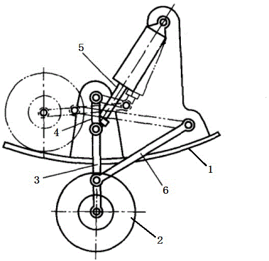
[0012] Instructions attached figure 1 The reference signs in include: body 1, roller 2, connecting rod 3, crank 4, cylinder piston rod 5, swing rod 6.

[0013] The embodiment is basically as attached figure 1 Shown: the moving mechanism of the concrete pavement cutting machine, including the body 1 of the cutting machine, the roller 2 is arranged under the body, the axis of the roller is connected with the rotating shaft through the flat key, and the rotating shaft is hinged with the lower end of the connecting rod 3 as a whole , the upper end of the connecting rod and the lower end of the crank 4 are hinged by a pin.

[0014] The middle part of the connecting rod protrudes to form a cylindrical pin shaft. The left end of the swing rod 6 is hinged to the cylindrical pin shaft. The right end of the swing rod is connected to the right side of the body through a hinge bolt...


PUM


Abstract

The invention belongs to the technical field of concrete processing machinery, and particularly relates to a concrete pavement cutter travel mechanism. The concrete pavement cutter travel mechanism comprises a cutter body, wherein a roller is arranged below the machine body, the axis of the roller is connected with a rotating shaft through a flat key, the upper side of a stander is hinged to a crankshaft, the lower end of the crankshaft is hinged with a connecting rod in a suspension manner, the lower end of the connecting rod is hinged to the rotating shaft, the lower end of the crankshaft is also hinged with an air cylinder piston rod, and the air cylinder piston rod is obliquely arranged on the right side of the crankshaft; the machine body on the right lower side of the crankshaft is hinged with a swinging rod, and the free end of the swinging rod is hinged to the middle part of the connecting rod. By adopting the concrete pavement cutter travel mechanism, the roller can be automatically folded and unfolded and can be prevented from being damaged.

Description

technical field [0001] The invention belongs to the technical field of concrete processing machinery. Background technique [0002] "Concrete cutting" refers to the construction technology of cutting concrete components, walls, roads, etc. by using tools such as hydraulic wall saws, electric disc saws, water drills or road cutters. It has strong cutting ability, no static damage, and high efficiency. High, water cooling, no construction dust and other characteristics. The joints cut into concrete pavements are called 'condensation joints'. During the setting and hardening process of concrete, the hydration of cement releases a large amount of heat, which causes the temperature of concrete to rise; most of the hydration reaction of cement ends, and the temperature of concrete begins to drop. During the cooling process, the concrete has solidified and hardened, and the shrinkage caused by the cooling will cause the concrete to crack, and the direction of the cracks is relati...

Claims


Application Information

Patent Timeline
Patent Type & Authority Applications(China)
IPC IPC(8): E01C23/09
CPCE01C23/0933
Inventor 赵子明
Owner CHONGQING CANHONG MACHINERY MFG
Why Eureka
Try Eureka