Telescopic locking device

A locking device and telescopic technology, applied in the direction of quick-acting fasteners, etc., can solve the problems of heavy weight, unable to meet special design requirements, and the locking is not firm, and achieve the effect of fast locking and relaxation

Inactive Publication Date: 2015-04-22
YUNNAN AEROSPACE IND
View PDF9 Cites 8 Cited by
  • Summary
  • Abstract
  • Description
  • Claims
  • Application Information

AI Technical Summary

Problems solved by technology

The locking devices purchased on the market are all exposed and embedded; they are bulky and heavy; the locking is not firm and cannot meet special design needs

Method used


Image

  • Telescopic locking device
  • Telescopic locking device
  • Telescopic locking device

Examples


Embodiment Construction

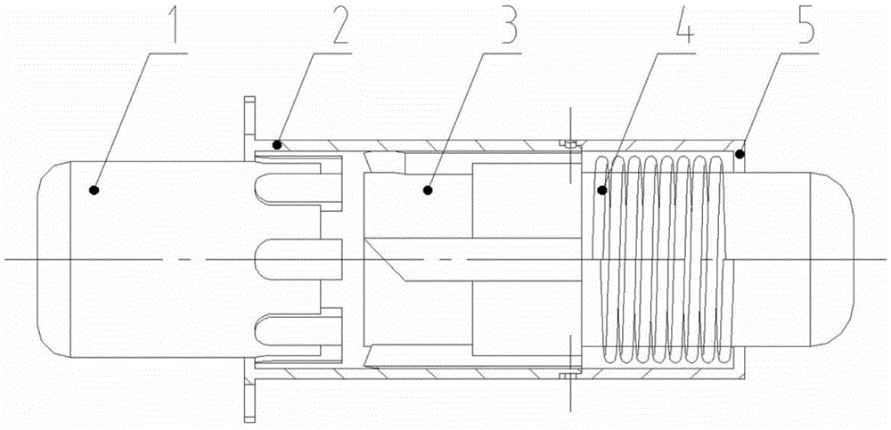
[0025] See Figure 1 to Figure 10 , a telescopic locking device, the present invention is characterized in that it is composed of a pressing head 1, a helical tooth guide rail cover 2, a telescopic lock tongue 3, a compression spring 4, and a locking sleeve 5; wherein:

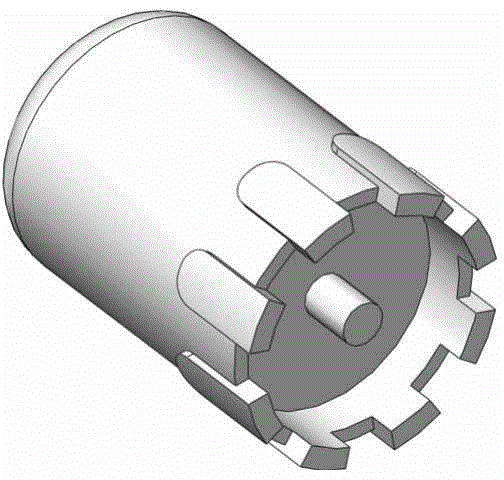
[0026] The pressing head 1 is a circular cylinder, the circular cylinder is fixed with a locking tooth 1.1 at the lower end of the circular cylinder, and a connecting pin 1.2 is arranged in the middle of the bottom end of the circular cylinder;

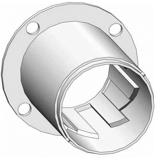
[0027] The helical tooth guide rail sleeve 2 is a sleeve 2.1 and a flange 2.2 connected to the end of the sleeve, and the inner wall ring of the sleeve 2.1 is provided with a card slot 2.3 for the locking teeth 1.1 to embed;

[0028] The retractable deadbolt 3 includes a circular cylinder 3.1 and a step 3.3 ringed on the circular cylinder 3.1, and a dial tooth 3.2 with an oblique plug is arranged on the upper ring of the step 3.3;

[0029] The compression spring 4 is...


PUM


Abstract

A telescopic locking device is formed by connecting a pressing head (1), a skewed tooth guide rail sleeve (2), a telescopic lock tongue (3), a compression spring (4) and a locking sleeve (5). The pressing head (1) is a cylinder. A latch (1.1) is fixed to the lower end of the cylinder in a surrounding mode. A connection pin (1.2) is arranged at the center of the bottom end of the cylinder. The skewed tooth guide rail sleeve (2) is composed of a sleeve (2.1) and a flange (2.2) connected to the end of the sleeve. A clamping groove (2.3) allowing the latch (1.1) to be embedded therein is annularly formed in the inner wall of the sleeve (2.1). The telescopic lock tongue (3) comprises a cylinder body (3.1) and a step (3.3) annularly arranged on the cylinder body (3.1). The step (3.3) is annularly provided with a shifting tooth (3.2) with an oblique plug. The compression spring (4) is arranged on the cylinder body (3.1) of the telescopic lock tongue (3) in a sleeving mode. The locking sleeve (5) is a circular sleeve. The telescopic locking device has the advantage of being capable of achieving quick locking and releasing in a point contact mode.

Description

technical field [0001] The invention belongs to the technology of fast retractable locking. Background technique [0002] The invention is mainly used for field cooking equipment, under the condition of field training, the equipment needs to be quickly deployed and withdrawn. The locking devices purchased on the market are all exposed and embedded; they are bulky and heavy; the locking is not firm and cannot meet special design needs. Contents of the invention [0003] The purpose of the present invention is to provide a simple and convenient telescopic lock that can not only quickly retract and lock, but also achieve the advantages of other locking devices in order to overcome the above-mentioned existing locking devices that cannot meet the special design requirements. stop device. [0004] The purpose of the present invention is achieved through the following technical solutions. [0005] A telescopic locking device, the present invention is characterized in that it ...

Claims


Application Information

Patent Timeline
Patent Type & Authority Applications(China)
IPC IPC(8): F16B21/08
CPCF16B21/08
Inventor 周剑
Owner YUNNAN AEROSPACE IND
Why Eureka
Try Eureka