Phase detector for all-digital phase locked and delay locked loops

Inactive Publication Date: 2006-01-17
MICRON TECH INC
View PDF21 Cites 22 Cited by
  • Summary
  • Abstract
  • Description
  • Claims
  • Application Information

AI Technical Summary

Benefits of technology

[0015]The present invention provides a novel phase detector using a two-way arbiter designed to discriminate a small phase error and provide all the features required by an all digital loop. The phase detector of the present invention can detect phase error down to 10 pico-seconds and produce UP and DOWN signals having a pulse width equal to one-half of the cycle of the clock signals, regardless of how close the loop is to “lock.” An n-bit counter, shift register, or other device provides noise filtering to select certain of the UP / DOWN signals to generate FAST and SLOW control signals to control the loop. The phase detector of the present invention provides for fast locking and stable operation of the loop with low jitter. Those, and other advantages and benefits, will be apparent from the Description of the Preferred Embodiment appearing hereinbelow.

Problems solved by technology

A problem occurs when traditional phase detectors are used for all digital PLL's and DLL's.

Method used


Image

  • Phase detector for all-digital phase locked and delay locked loops
  • Phase detector for all-digital phase locked and delay locked loops
  • Phase detector for all-digital phase locked and delay locked loops

Examples


Embodiment Construction

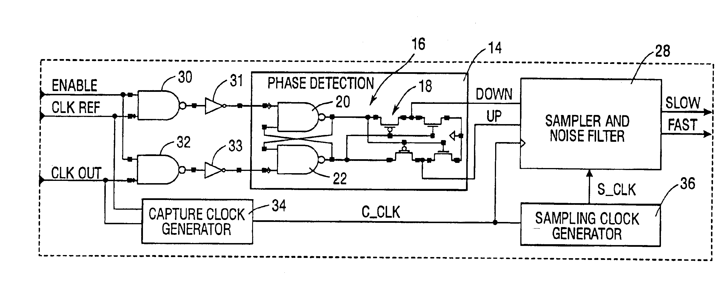
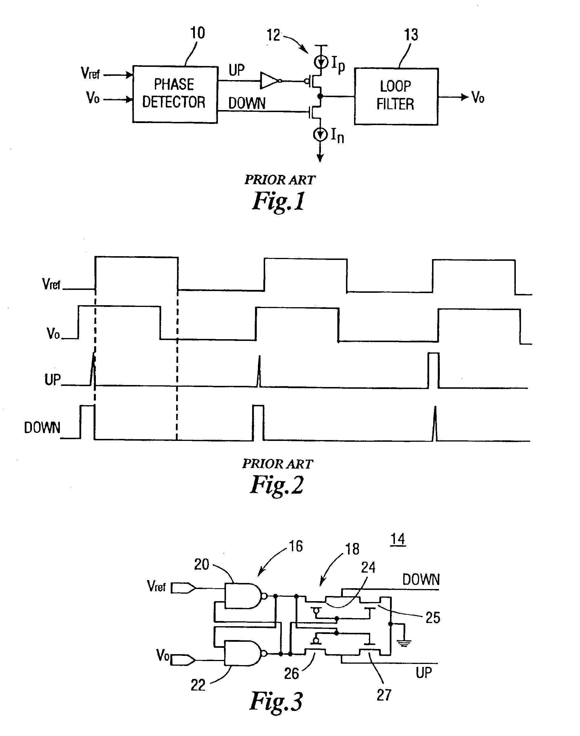
[0027]FIG. 3 illustrates a phase detector 14 constructed according to the teachings of the present invention. The phase detector 14 is comprised of a phase detector circuit 16 and an arbiter circuit 18. The phase detector circuit 16 is comprised of two cross-coupled NAND gates 20 and 22. Four transistors, two p-type 24, 26 and two n-type 25, 27, are connected to provide a two-way arbiter circuit 18. The arbiter circuit 18 produces the UP signal and DOWN signal in a manner such that at the rising edges, the UP signals and DOWN signals can never be high at the same time. Additionally, the width of the pulse for the “winning” signal, either UP or DOWN depending on current phase relationship, is at least equal to one-half of the cycle of the reference and output signals.

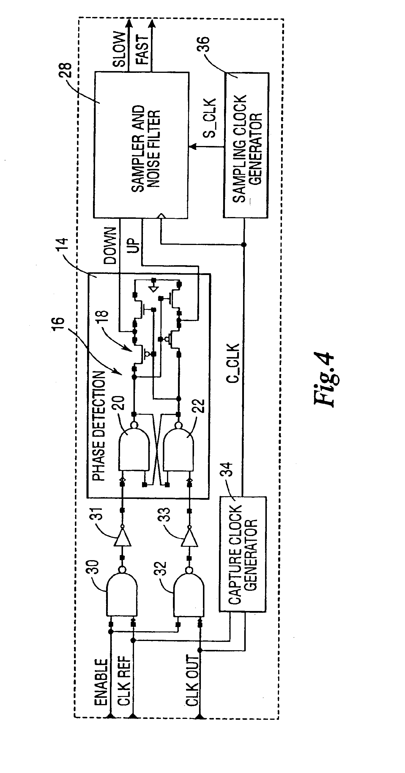
[0028]Because the phase detector 14 of the present invention is very sensitive to small phase error, a sampling and noise filtering circuit is preferably added to provide stable operation. FIG. 4 illustrates a phase dete...


PUM


Abstract

A phase detector is comprised of two cross-coupled gates which are capable of phase discrimination down to a level of approximately 10 picoseconds. An arbiter circuit, responsive to the cross-coupled gates, generates mutually exclusive UP and DOWN pulse signals. The UP and DOWN pulse signals may be filtered and used to control the delay line of an all digital delay locked or phase locked loop.

Description

[0001]This application is a divisional of Ser. No. 09 / 652,364 filed Aug. 31, 2000 now U.S. Pat. 6,779,126.BACKGROUND OF THE INVENTION[0002]1. Field of the Invention[0003]The present invention is directed to phase detectors and, more particularly, to phase locked and delay locked loops comprised of all digital components.[0004]2. Description of the Background[0005]A phase locked loop is a circuit designed to minimize the phase difference between two signals. When the phase difference approaches zero, or is within a specified tolerance, the phase of the two signals is said to be “locked”. A delay locked loop is similar to a phase locked loop, but instead of producing an output signal which has the same phase as an input or reference signal, the delay locked loop passes a reference or input signal into a delay line, and the output of the delay line has some predefined phase delay with respect to the reference or input signal.[0006]Phase locked loops (PLL's) and delay locked loops (DLL'...

Claims


Application Information

Patent Timeline
Patent Type & Authority Patents(United States)
IPC IPC(8): G11C7/00G06F1/04G11C7/22G11C8/00G11C11/00H03L7/081H03L7/089H03L7/099
CPCG11C7/22G11C7/222H03L7/089H03L7/0995H03L7/0814H03L2207/50H03L7/0816
Inventor LIN, FENGBAKER, R. JACOB
Owner MICRON TECH INC
Why Eureka
Try Eureka