Combined power generation device

A power generation device and combined technology, which is applied in the direction of mobile frame, engine frame, machine/engine, etc., can solve the problems of difficult assembly of power generation equipment, achieve low labor intensity in handling, avoid slippage, and reduce handling weight.

Inactive Publication Date: 2015-04-22
CHONGQING ZHIREN ELECTRIC EQUIP
View PDF7 Cites 0 Cited by
  • Summary
  • Abstract
  • Description
  • Claims
  • Application Information

AI Technical Summary

Problems solved by technology

[0005] In view of this, the purpose of the present invention is to provide a combined power generation device to solve the problems of the existing small power generation equipment in the field, such as the invariable transfer of the three areas, and the difficulty in assembling the power generation equipment.

Method used


Image

  • Combined power generation device
  • Combined power generation device
  • Combined power generation device

Examples


Embodiment Construction

[0016] The present invention will be further described below in conjunction with the accompanying drawings and embodiments.

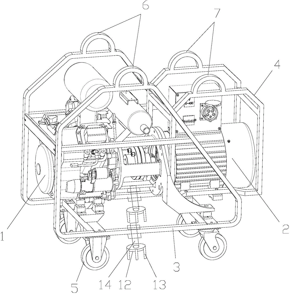
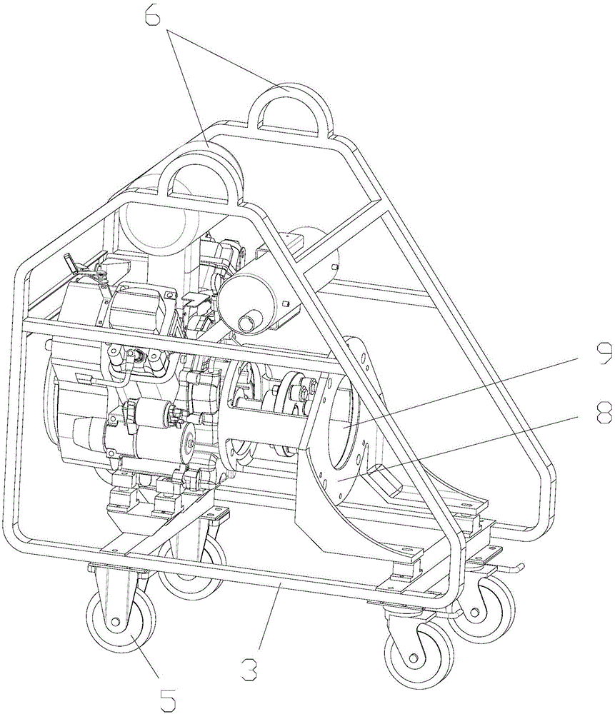
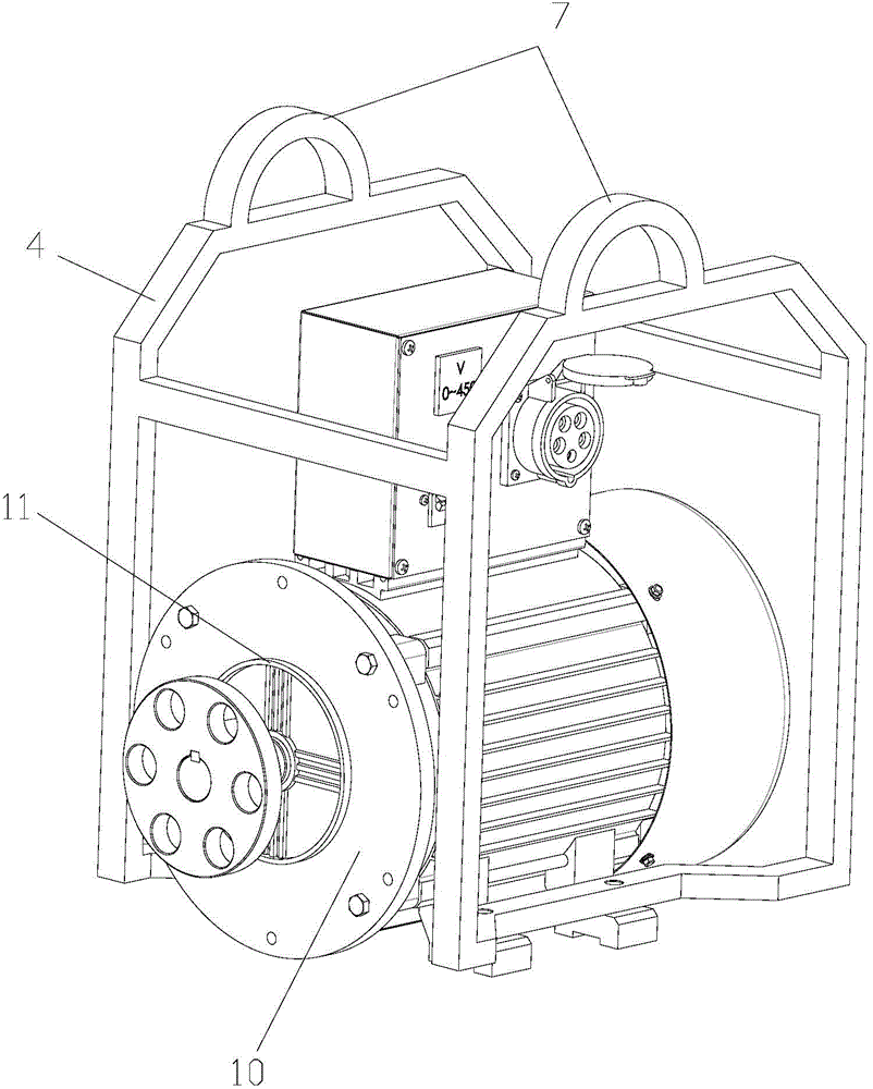
[0017] As shown in the figure, the combined power generating device of this embodiment includes an engine 1 and a generator 2 connected to the engine 1, and also includes a main frame 3 and a sub-frame 4 detachably connected to the main frame 3, and the engine 1 is fixed on the main frame 3, the generator 2 is fixed on the sub-frame 4, the bottom of the main frame 1 is provided with traveling wheels 5, and the main frame 1 is also provided with a first lifting lug 6, so The sub-frame 4 is provided with a second lifting ear 7 .

[0018] The combined power generation device of this embodiment can be disassembled and transported separately when transporting in mountainous areas. Separate transport can greatly reduce the transporting weight, and the transporting labor intensity is low. problem; at the same time, the walking wheels it sets can make the tran...


PUM


Abstract

The invention discloses a combined power generation device which comprises an engine, a generator connected with the engine, a main rack and an auxiliary rack in detachable connection with the main rack. The engine is fixed on the main rack, and the generator is fixed on the auxiliary rack. A first lifting lug is arranged on the main rack, and a second lifting lug is arranged on the auxiliary rack. When being carried in mountainous areas, the engine and the generator of the combined power generation device can be separately transported, thus greatly reducing the carrying weight and the labor intensity and solving the carrying problem of small power generation devices in mountainous areas. In addition, during assembling of the engine and the generator, a convex spigot on a second flange is inserted into a positioning hole formed in a first flange in a matched way, so a power output shaft of the engine and a rotor shaft of the generator can be aligned automatically, and the coaxiality of the power output shaft and the rotor shaft can be guaranteed. The combined power generation device can improve the assembling efficiency of the engine and the generator and reduce labor intensity during assembling.

Description

technical field [0001] The invention relates to a power generating device, in particular to a combined power generating device. Background technique [0002] For wild alpine areas, since there is no power facility, when electricity is needed, usually only mobile small-scale power generation equipment can be used to generate electricity by itself. [0003] However, the existing small-scale power generation equipment has a large overall weight of its engine and electric motor, and it is relatively difficult to move, which causes great difficulties for field power generation. [0004] And the existing small-sized power generation equipment, because the weight of generator and engine is bigger when assembling, the power output shaft of engine and the rotor shaft of generator are centered difficult when being connected, and assembling difficulty is big, and assembling work efficiency is low. Contents of the invention [0005] In view of this, the purpose of the present inventi...

Claims


Application Information

Patent Timeline
Patent Type & Authority Applications(China)
IPC IPC(8): F16M3/00F02B63/04
Inventor 李龙李曦
Owner CHONGQING ZHIREN ELECTRIC EQUIP
Why Eureka
Try Eureka