
Optical design method enabling half-intensity angle to be located on 8-degree round spot

A technology of optical design and angle, applied in the direction of optics, optical signals, optical components, etc.

Active Publication Date: 2015-04-22
GUANGDONG RAYTON INTELLIGENT OPTO CO LTD
View PDF3 Cites 2 Cited by
  • Summary
  • Abstract
  • Description
  • Claims
  • Application Information

AI Technical Summary

Problems solved by technology

At present, ordinary optical accessories such as reflectors and lenses cannot meet the requirements, so it is necessary to design a special optical accessory to meet the optical requirements of off-road vehicles.

Method used


Image

  • Optical design method enabling half-intensity angle to be located on 8-degree round spot
  • Optical design method enabling half-intensity angle to be located on 8-degree round spot
  • Optical design method enabling half-intensity angle to be located on 8-degree round spot

Examples


Embodiment Construction

[0042] The present invention will be further described below in conjunction with the accompanying drawings of the description.

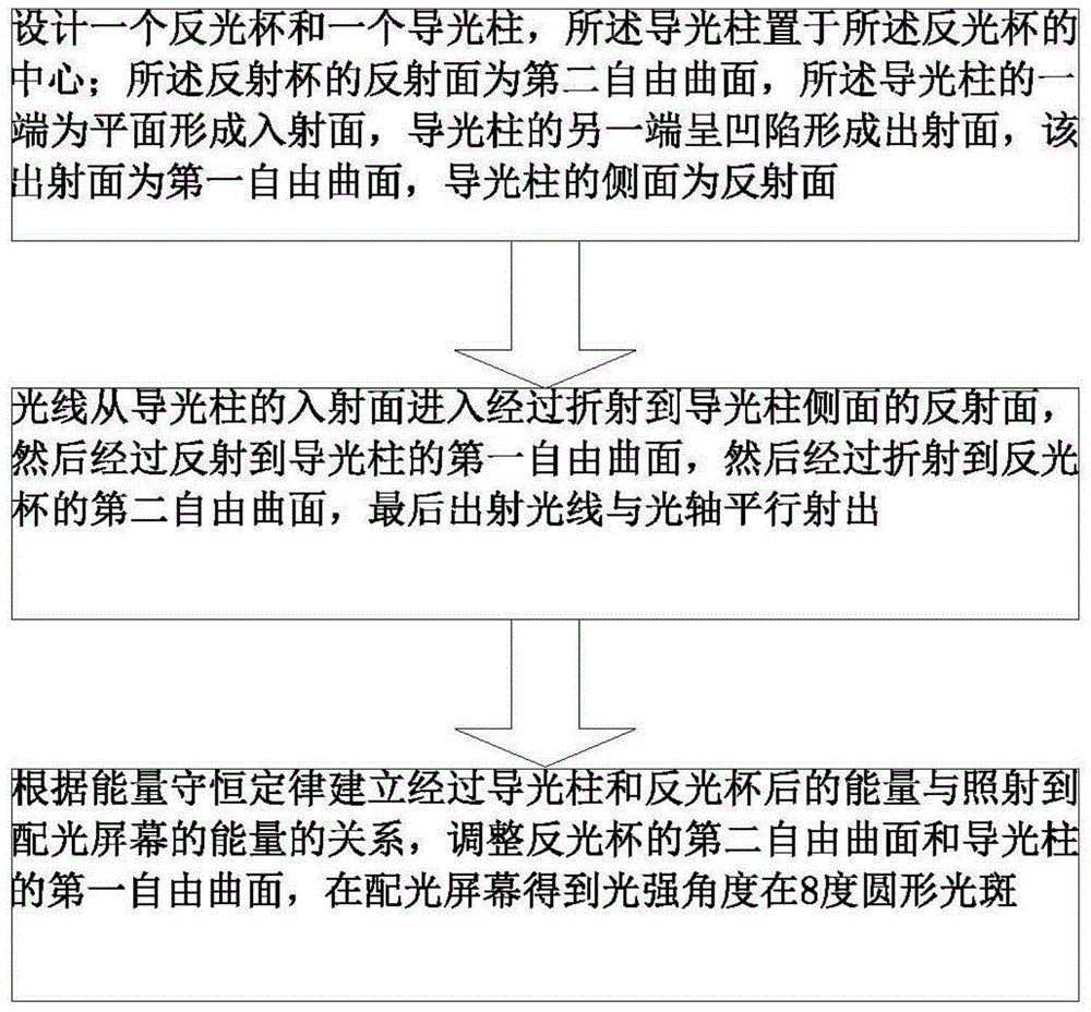
[0043] like figure 1 As shown, an optical design method that satisfies the half-light intensity angle of a circular spot at 8 degrees is characterized in that it includes the following steps:

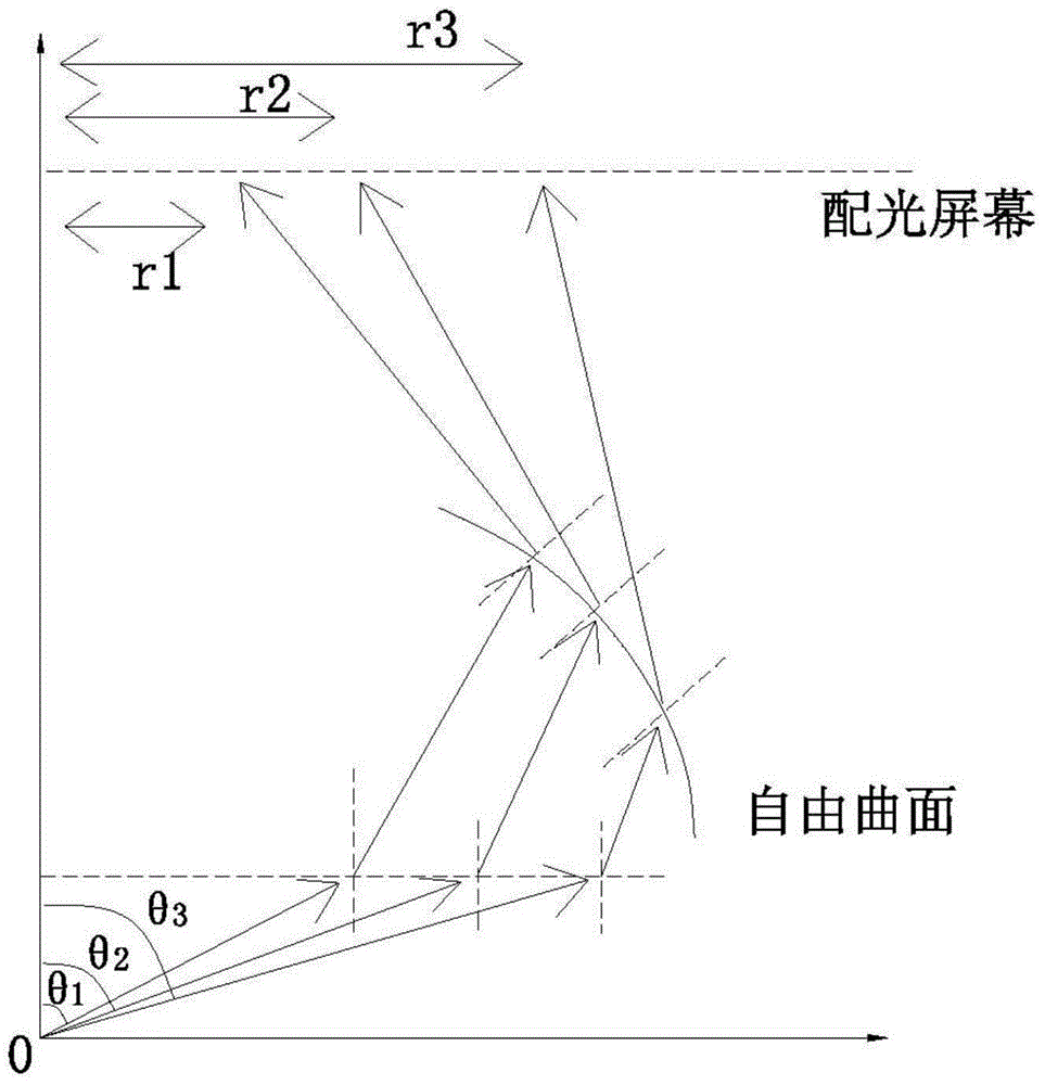
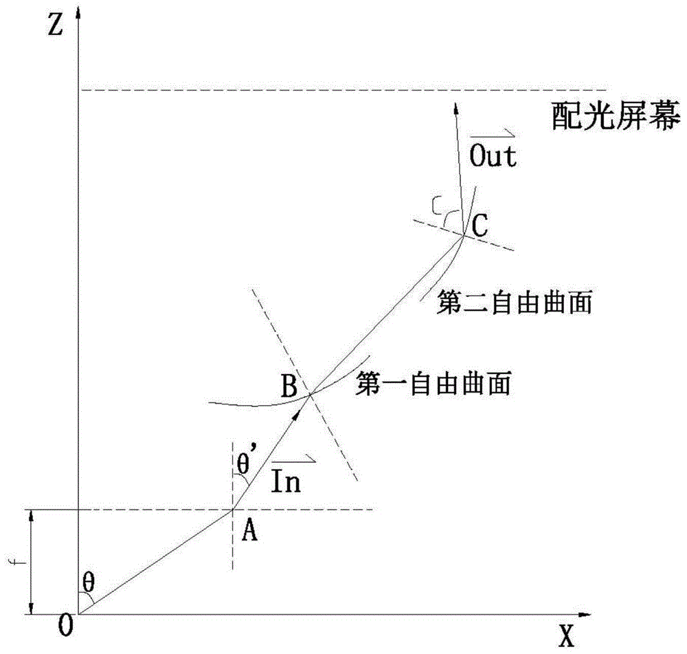
[0044] (1) if Figures 5 to 7 As shown, a reflective cup 1 and a light guide post 2 are designed, and the light guide post 2 is placed at the center of the reflective cup 1; the reflective surface of the reflective cup 1 is a second free-form surface 11, and the light guide post 2 One end is a plane to form an incident surface 21, the other end of the light guide column 2 is concave to form an exit surface, the exit surface is a first free curved surface 23, and the side of the light guide column 2 is a reflective surface 22;

[0045] (2) The light enters from the incident surface 21 of the light guide column 2 and enters the reflective surface 22 on the sid...


PUM


Abstract

An optical design method enabling a half-intensity angle to be located on a 8-degree round spot comprises the steps that (1) a reflection cup and a light guiding pillar are designed, wherein the light guiding pillar is arranged at the center of the reflection cup, the reflection surface of the reflection cup is a second free-form surface, one end of the light guiding pillar is a plane and serves as an incident plane, the other end of the light guiding pillar is concave and serves as an exit surface which is a first free-form surface, and the side face of the light guiding pillar is a reflection surface; (2) light enters through the incident plane of the light guiding pillar and is refracted to the reflection surface on the side face of the light guiding pillar, reflected to the first free-form surface of the light guiding pillar, refracted to the second free-form surface of the reflection cup, and finally emitted in the direction parallel to the optical axis; (3) the relationship between the energy obtained after light passes through the light guiding pillar and the reflection cup and the energy irradiated on a light distribution screen is established according to the energy conservation law, the second free-form surface of the reflection cup and the first free-form surface of the light guiding pillar are adjusted, and the half-intensity angle is obtained on the 8-degree round spot of the light distribution screen.

Description

technical field [0001] The invention relates to the field of LED lighting, in particular to an optical design method for a circular light spot with a half light intensity angle of 8 degrees. Background technique [0002] LED lighting is used for floodlighting in car lights, and the most commonly used LED car lights include car headlights, car signal lights and conventional car lights. For off-road vehicle lighting fixtures, the light efficiency requirements are relatively strict, and the emitted light meets the half-intensity angle of a circular spot at 8 degrees. At present, ordinary optical accessories such as reflectors and lenses cannot meet the requirements, so it is necessary to design a special optical accessory to meet the optical requirements of off-road vehicles. Contents of the invention [0003] The technical problem to be solved by the present invention is to provide an optical design method that satisfies a circular light spot with a half light intensity ang...

Claims


Application Information

Patent Timeline
IPC IPC(8): F21V7/04F21V8/00F21W101/02F21Y101/02F21W107/10
CPCF21S41/141F21S41/24F21S41/32F21S43/14F21S43/237F21S43/31F21W2107/10F21Y2101/00
Inventor 周盛华陈焕杰石智伟
Owner GUANGDONG RAYTON INTELLIGENT OPTO CO LTD
Learn More