Cooling wheel testing device

A test device and wheel technology, applied in wheel testing, etc., can solve problems such as increased tire pressure, tire blowout, and increased cord stress

Inactive Publication Date: 2015-04-22
GUANGXI UNIVERSITY OF TECHNOLOGY
View PDF12 Cites 1 Cited by
  • Summary
  • Abstract
  • Description
  • Claims
  • Application Information

AI Technical Summary

Problems solved by technology

The rise of tire temperature will also easily cause the tire pressure to rise accordingly, which will increase the stress on the cord and make it easier for high-speed tires to blow out

Method used


Image

  • Cooling wheel testing device

Examples


Embodiment 1

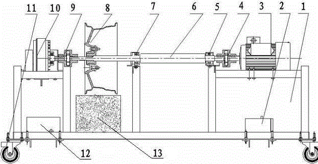
[0030] A cooling wheel test device, comprising a bracket 1, a frequency converter 2, a motor 3, couplings 4, 9, bearings 5, 7, a stepped shaft 6, a torque meter 10, a wheel 11, a load detector 12 and a road condition simulation platform 13;

[0031] The inverter 2 is fixedly installed under the bracket 1;

[0032] The motor 3 and the torque meter 10 are horizontally opposed, fixedly installed on the left and right ends of the bracket 1 respectively, and are on the same axis;

[0033] The stepped shaft 6 includes a small-diameter shaft section and a large-diameter shaft section, supported by two bearings 5 ​​and 7 installed on the bracket 1, and the two ends are respectively connected to the output shaft of the motor 3 and the input shaft of the torque meter 10 through couplings 4 and 9 , the cooling wheel 8 is installed on the small-diameter shaft section for testing;

[0034] The load detector 12 is arranged on the left side of the lower part of the bracket 1; the road cond...


PUM


Abstract

The invention relates to a cooling wheel testing device. The cooling wheel testing device comprises a support, a frequency converter, a motor, couplers, bearings, a stepped shaft, a torque meter and wheels, wherein the frequency converter is fixedly mounted below the support; the motor and the torque meter are horizontally opposite to each other, fixedly mounted at the left end and the right end of the support respectively and located in the same axis; the stepped shaft is supported by the two bearings mounted on the support, the two ends of the stepped shaft are connected with an output shaft of the motor and an input shaft of the torque meter through the couplers respectively, and a cooling wheel is mounted on the small-diameter shaft section of the stepped shaft for testing; the wheels are fixedly mounted at the lower ends of the four corners of the support respectively, the support can be moved through the wheels, and meanwhile a locking structure is arranged on each wheel; a base of the support can be stretched to adapt to stepped shafts with different lengths. The cooling wheel testing device is reasonable in structural design, low in manufacturing cost and good in detection effect.

Description

technical field [0001] The invention relates to a cooling wheel test device, in particular to a device capable of measuring the temperature of the wheel surface and the temperature of the brake position of the cooling wheel under different speeds, temperatures and road conditions, and calculating the temperature of the brake position at various speeds. Test device for the extent of temperature reduction of the wheel surface. Background technique [0002] The development of the automobile industry has brought a lot of convenience and joy to people's travel. Unfortunately, traffic safety is always threatening people's property and life safety. In recent years, the tire blowout accidents of vehicles have increased suddenly. According to statistics, tire blowout accounts for more than 70% in traffic accidents on expressways. Car accidents caused by frequent tire blowouts have aroused people's vigilance and confusion. Why were tire blowouts rare in the past when the road condi...

Claims


Application Information

Patent Timeline
Patent Type & Authority Applications(China)
IPC IPC(8): G01M17/013
Inventor 李健韦辽熊科李桂丽
Owner GUANGXI UNIVERSITY OF TECHNOLOGY
Why Eureka
Try Eureka