A Method for Predicting Circuit Interference in Chassis with Penetrating Cables Based on Field-circuit Coupling

A circuit interference and field-circuit coupling technology, applied in electrical digital data processing, special data processing applications, instruments, etc., can solve the problem that the high-frequency calculation accuracy cannot respond, the electromagnetic effect modeling of the internal electronic system, and the electromagnetic sensitivity of the internal space can be solved. performance cannot be guaranteed, to achieve the effect of improving accuracy and reducing complexity

Active Publication Date: 2017-09-15
XIDIAN UNIV
View PDF2 Cites 0 Cited by
  • Summary
  • Abstract
  • Description
  • Claims
  • Application Information

AI Technical Summary

Problems solved by technology

[0006] The purpose of the present invention is to overcome the electromagnetic susceptibility problem in the prior art, which cannot guarantee the calculation accuracy of the high-frequency band for the electromagnetic susceptibility of the internal space and cannot reflect the high-frequency effects such as coupling and radiation between the microstrip lines of the internal electronic system , the problem of not being able to fully model the electromagnetic effects of the internal electronic system

Method used


Image

  • A Method for Predicting Circuit Interference in Chassis with Penetrating Cables Based on Field-circuit Coupling
  • A Method for Predicting Circuit Interference in Chassis with Penetrating Cables Based on Field-circuit Coupling
  • A Method for Predicting Circuit Interference in Chassis with Penetrating Cables Based on Field-circuit Coupling

Examples


Embodiment 1

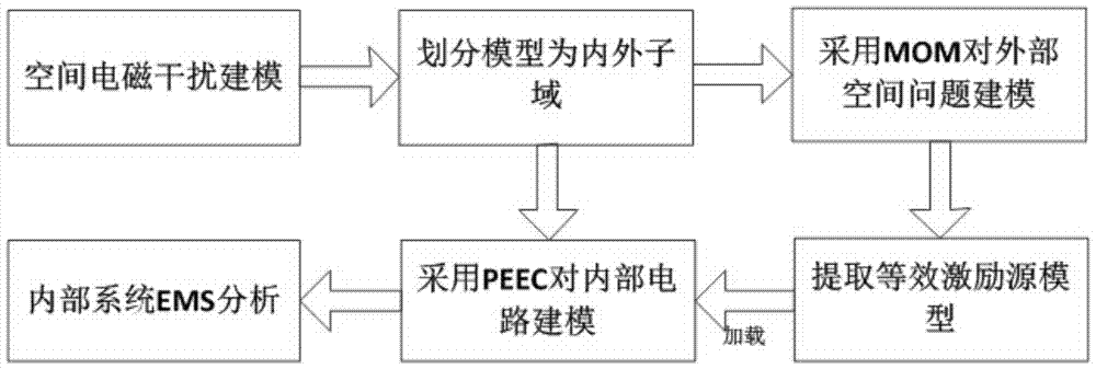
[0043] In order to provide such figure 1 The solution to the EMS problem of the circuit inside the chassis with penetrating cables is shown. This method establishes the equivalent excitation source model of the external cable coupling electromagnetic interference through the moment method, and uses the partial equivalent source circuit method (PEEC) to analyze the electronic equipment chassis. The internal circuit is modeled, and finally the cable equivalent excitation source is loaded on the internal circuit model to solve the response of external electromagnetic interference on the circuit in the shielded chassis

[0044] The method for predicting circuit interference in a cabinet with penetrating cables based on field-circuit coupling includes the following steps:

[0045]Step 101, modeling the electromagnetic wave interference source outside the chassis to determine the electromagnetic interference in the external space;

[0046] Step 102, dividing the research object mod...

Embodiment 2

[0068] 1. Simulation object

[0069] Such as Figure 4 , as shown in Figure 5, where the structural size parameters of the shielding box are: L×W×H=400mm×312mm×325mm, located in the outer space of the shielding box Ω 2 Medium cable length l 2 The diameter is 500mm, the radius is 0.5mm, the SMA connector (model KFD220) is located on the shielding case, the center dielectric radius is 2mm, the radius of the conductive copper core is 0.5mm, in the inner space of the shielding case Ω 1 Built-in double-layer PCB board, its length is 50mm, width is 50mm, thickness is 2mm, relative permittivity ε r is 4.5. The PCB board contains two microstrip lines with a length of 50mm and a distance of 3mm. The cross-sectional size is 1mm×0.2mm. Except for the port connected to the cable, the other three terminals are connected to the ground plane through a 50Ω resistor. Electromagnetic interference is a plane wave, which is determined by the following formula:

[0070]

[0071] in, To i...


PUM


Abstract

The present invention relates to the field of chassis electromagnetic compatibility design, specifically a field-circuit coupling-based method for predicting circuit interference in a chassis with penetrating cables. By modeling the internal electronic system with the Partial Equivalent Source Circuit (PEEC) method, its The high-frequency equivalent circuit model of the circuit microstrip line, and using it to replace the low-frequency circuit theory of the traditional method, can not only calculate the electromagnetic susceptibility (EMS) problem of the complex electronic system in the box, but also fully describe the high-frequency effect of the internal complex circuit, Such as high-frequency crosstalk between lines, etc., improve the accuracy of the traditional field-circuit hybrid analysis method in the high-frequency band; by dividing the chassis with through cables into internal and external space sub-domains, and using the moment method for the external space cables and chassis shell (MOM) for analysis, while the internal circuit is modeled using the partial equivalent source circuit method (PEEC), which effectively reduces the complexity of the model.

Description

technical field [0001] The invention relates to the field of chassis electromagnetic compatibility design, in particular to a method for predicting interference of circuits in a chassis with through cables based on field-circuit coupling. Background technique [0002] Military electronic equipment works in a harsh electromagnetic environment. High-power microwave weapons and high-altitude nuclear explosions will generate strong electromagnetic interference. Electronic equipment in a shielded chassis will be protected to a certain extent due to the electromagnetic shielding effect of the chassis, but the through-wire between systems The electromagnetic interference in the cable coupling space generates an induced current, which is transmitted to the electronic system in the chassis along the cable. The internal circuit will generate a voltage (current) response to the above interference. These interference signals will degrade the system performance in the slightest, and make ...

Claims


Application Information

Patent Timeline
Patent Type & Authority Patents(China)
IPC IPC(8): G06F19/00
Inventor 李鹏杨福荣段宝岩李勋王朝斌
Owner XIDIAN UNIV
Why Eureka
Try Eureka