
A monitoring and protection device for starter motors

A technology of protection device and starting motor, applied in emergency protection circuit devices, electrical components, etc., can solve the problems of motor coil burning and fire, battery melting and burning, etc., to avoid safety accidents and prevent large current discharge.

Active Publication Date: 2019-02-22
SHANGHAI MICROPOWERS
View PDF2 Cites 0 Cited by
  • Summary
  • Abstract
  • Description
  • Claims
  • Application Information

AI Technical Summary

Problems solved by technology

Because the traditional starter motor has no monitoring and protection device inside the motor, when the internal switch and actuator fail, due to the lack of effective protection device, the high current at the moment of starting will burn the relay and the magnetoelectric switch instantly, and even the motor coil will melt and catch fire. Accidents such as battery meltdown, so it is necessary to strengthen its safety protection such as overcurrent
[0004] In addition, the general traditional starter motor is composed of a relay, an electromagnetic switch, a planetary gear reduction device, and a coil assembly, resulting in a compact structure and a very complicated closed space environment, and it is impossible to observe its interior visually. Therefore, the relay, electromagnetic switch Whether it is energized, whether its contacts are stuck, or even short-circuited, cannot be monitored and diagnosed in time and accurately. Therefore, in order to ensure the reliability and safety of the system control, it is necessary to check the operating status of the internal equipment of the starter motor, the large current of the circuit, etc. Real-time and effective monitoring to prevent safety accidents

Method used


Image

  • A monitoring and protection device for starter motors

Examples


Embodiment Construction

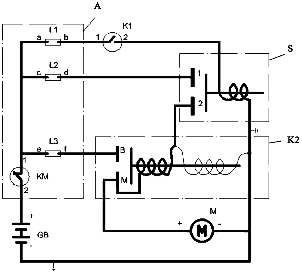
[0014] figure 1 Shown is the circuit diagram of the starter motor monitoring and protection device of the present invention, the starter motor circuit is mainly composed of electrical components such as relay S, magnetoelectric switch K2, motor M, monitoring and protection device circuit A, and peripheral control switch K1 and storage battery GB, It mainly performs on / off control of the main circuit of the starter motor, alarms and indications of important parameters exceeding limits, and data monitoring.

[0015] Monitoring and protection device circuit A mainly includes shunt L1, L2, L3 and circuit breaker KM, one end of shunt L1, L2, L3 is connected together, that is, end a of shunt L1 and end c of shunt L2, shunt The e terminal of L3 is connected, and then connected in series with the 1 terminal of the circuit breaker KM, the 2 terminal of the circuit breaker KM is connected to the positive pole + of the peripheral battery; at the same time, the b terminal of the shunt L1 ...


PUM


Abstract

The invention discloses a monitoring and protecting device for a starter motor. The monitoring and protecting device comprises a relay S connected with the motor M, a magnetoelectric switch K2, a master controller and a monitoring and protecting device circuit A, wherein the monitoring and protecting device circuit A comprises a current divider L1, a current divider L2, a current divider L3 and a circuit breaker KM; one end of the current divider L1, one end of the current divider L2 and one end of the current divider L3 are connected together, that is, the end a of the current divider L1 is connected with the end c of the current divider L2 and the end e of the current divider L3 and then is connected with the first end of the circuit breaker KM in series, and the second end of the circuit breaker KM is connected into the positive pole + of a peripheral storage battery GB; meanwhile, the end b of the current divider L1 is connected to the first end of a control switch K1 and connected with the control switch K1 in series; the end d of the current divider L2 is connected to the first end of the relay S and connected with the relay S in series; the end f of the current divider L3 is connected to the end B of the magnetoelectric switch K2 and connected with the magnetoelectric switch K2 in series.

Description

technical field [0001] The invention relates to a starter motor, in particular to a monitoring and protection device for a starter motor. Background technique [0002] Generally, starter motors are mainly used for short-term dragging before the operation of gasoline engines and diesel engines, etc., requiring starter motors to be small in size, compact in structure, and large in starting torque. high expectation. [0003] The starter motor generally adopts a DC series-excited motor. When the prime mover starts, the working parts in the motor need to complete the conversion of electrical energy to mechanical energy in a short time, and the internal circuit part will be subjected to a high current impact of up to 700A-1000A in an instant. , The instantaneous torque of the mechanical part is as high as 60Nm. Because the traditional starter motor has no monitoring and protection device inside the motor, when the internal switch and actuator fail, due to the lack of effective p...

Claims


Application Information

Patent Timeline
Patent Type & Authority Patents(China)
IPC IPC(8): H02H7/085
Inventor 黄振军林志民龚欢
Owner SHANGHAI MICROPOWERS
Learn More