Supercharge Your Innovation With Domain-Expert AI Agents!

Rotor locking sleeve structure for centrifuge

A technology of locking sleeves and centrifuges, applied in centrifuges and other directions, can solve the problems of difficulty in ensuring accuracy, difficult processing, and high processing accuracy requirements, and achieve the effects of easy disassembly, convenient processing, and guaranteed assembly concentricity

Inactive Publication Date: 2015-04-29
上海力申科学仪器有限公司
View PDF5 Cites 2 Cited by
  • Summary
  • Abstract
  • Description
  • Claims
  • Application Information

AI Technical Summary

Problems solved by technology

The disadvantage of this method is that it is difficult to process the tapered hole on the rotor, and it is difficult to ensure the accuracy; and it is inconvenient to disassemble the rotor during use.
The other is that the rotor and the main shaft are driven by machining key slots or pins. This method relies solely on the machining accuracy of the grooves or pin holes to ensure assembly accuracy, which requires high machining accuracy and is difficult to process.

Method used


Image

  • Rotor locking sleeve structure for centrifuge

Examples


Embodiment Construction

[0012] The rotor locking sleeve structure of the centrifuge of the present invention will be further described in detail below in conjunction with the accompanying drawings.

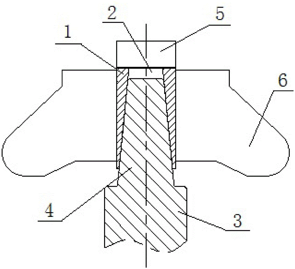
[0013] like figure 1 As shown, the rotor locking sleeve structure of the centrifuge of the present invention includes an elastic locking sleeve 1 with a clamping hole 2 in the shape of a truncated cone, and a locking screw or nut as a pressing device 5 . The end of motor main shaft 3 processes screw hole or screw rod, and pressing device 5, the assembly hole on the rotor 6 is processed into straight hole. The frustum-shaped clamping hole 2 of the locking sleeve 1 fits with the connecting end 4 of the frustum-shaped shape, and the outer circle of the locking sleeve 1 fits with the straight assembly hole of the rotor 6. 6 lock.

[0014] The assembly hole of the rotor of the rotor locking sleeve structure of the centrifuge of the present invention is made into a straight through hole, which is convenient ...


PUM


Abstract

The invention relates to a rotor locking sleeve structure for a centrifuge. The structure comprises a locking sleeve, a motor spindle and a compression unit. A truncated-cone-shaped snapping hole is formed in the locking sleeve. The connection end of the motor spindle is in a truncated cone shape, and the shape of the connection end is matched with the shape of the snapping hole. Internal threads are arranged in the compression unit, external threads are arranged at the end of the connection end, the internal threads are matched with the external threads, and the compression unit is connected with the end of the connection end. The compression unit is a screw or a nut. By means of the structure, an assembly hole of the rotor of the structure is changed into a straight through hole, so that machining is facilitated; by the aid of the tapered sleeve connection, the assembly concentricity is guaranteed effectively; when the rotor is disassembled, only the locking screw or nut is needed to be screwed or loosened, and the locking sleeve is not needed to be dismounted, accordingly, the structure is simple and convenient to disassemble.

Description

technical field [0001] The invention is used in the technical field of refrigerated centrifuges, in particular to a centrifuge rotor locking sleeve structure. Background technique [0002] The principle of the centrifuge to separate the experimental samples is to drive the rotor to rotate at a high speed through the motor, so that the samples in the container are separated by a certain centrifugal force. [0003] For the rotor to participate in the rotation process of acceleration and deceleration driven by the motor, the rotor must be tightly fixed on the main shaft of the motor, and in order to ensure smooth and quiet rotation, the concentricity of the two must be guaranteed. At present, there are mainly two kinds of fixing methods. One is to make the joint between the motor shaft and the rotor into a tapered shape, and the tapered hole is processed on the rotor to fit it, and then compressed with a nut. The disadvantage of this method is that it is difficult to process t...

Claims


Application Information

Patent Timeline
IPC IPC(8): B04B7/00
Inventor 王鸿伟张金平
Owner 上海力申科学仪器有限公司
Features
  • R&D
  • Intellectual Property
  • Life Sciences
  • Materials
  • Tech Scout
  • Unparalleled Data Quality
  • Higher Quality Content
  • 60% Fewer Hallucinations
Learn More