Mold air and water combined cooling system and low-pressure wheel hub mold with same

A hybrid cooling and low-pressure wheel technology is applied in the field of automobile wheel hub molds, which can solve the problems of mechanical properties of product materials affecting product production efficiency, prolonged mold opening time, uneven cooling effect, etc. The effect of reducing the amount of voltage used and reducing the cost of electricity

Active Publication Date: 2015-04-29
KUNSHAN ZHONGYITE MACHINERY IND
View PDF13 Cites 6 Cited by
  • Summary
  • Abstract
  • Description
  • Claims
  • Application Information

AI Technical Summary

Problems solved by technology

However, the cooling rate of this cooling method is slow, which will lead to the extension of the mold opening time, thereby affecting the production efficiency of the product and the mechanical properties of the product material
[0003] In the prior art, there is a method of changing the compressed air to mixed and atomized water vapor to cool the cooling terminal. Although the cooling effect of water vapor is better than that of compressed air, the water vapor remaining in the channel will cause rust on the one hand, and on the other hand On the one hand, the residual position will also lead to uneven cooling effect

Method used


Image

  • Mold air and water combined cooling system and low-pressure wheel hub mold with same
  • Mold air and water combined cooling system and low-pressure wheel hub mold with same
  • Mold air and water combined cooling system and low-pressure wheel hub mold with same

Examples


Embodiment Construction

[0027] The technical solutions of the present invention will be further described below in conjunction with the accompanying drawings and through specific implementation methods.

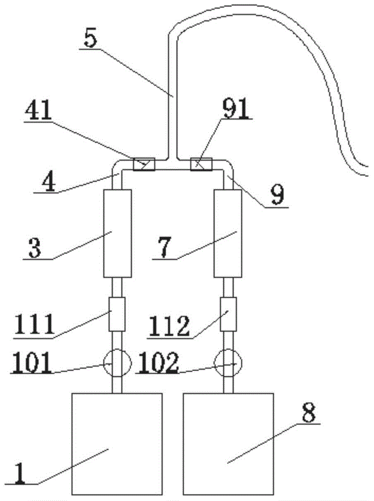
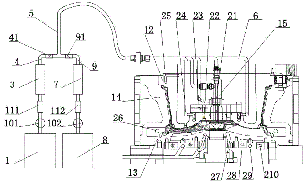
[0028] The invention provides a mold air-water mixing cooling system, such as figure 1 As shown, the system includes an external air pressure source machine 1, a first pressure gauge 101, a first flow meter 3, a first pipeline 4 and a main pipe 5, and the external air pressure source machine 1 passes through the first pipeline 4 and one end of the main pipe 5 The other end of the main pipe 5 includes no less than two shunt pipes 6; the first flowmeter 7 and the first pressure gauge 101 are arranged on the first pipe, and the shunt pipe 6 is connected to the cooling terminal of the mold. connection; the system also includes an external circulating cooling water machine 8, the external circulating cooling water machine 8 is connected to the second pipeline 9, and the second pipeline 9 is connected to ...


PUM


Abstract

The invention discloses a mold air and water combined cooling system. The mold air and water combined cooling system comprises an external air pressure source machine, a first pressure gauge, a first flow meter, a first pipe and a main pipe. The external air pressure source machine is connected to one end of the main pipe through the first pipe, the other end of the main pipe comprises at least two or more diversion pipes, the first pipe is provided with the first flow meter, and the diversion pipes are connected to mold hot junction cooling terminals. The mold air and water combined cooling system further comprises an external circulating cooling water machine. The external circulating cooling water machine is connected to a second pipe, the second pipe is connected to the first pipe in parallel and then is connected to the main pipe, a second pressure gauge, and a second solenoid control valve and a second flow meter are arranged on the second pipe sequentially. The first pipe is also provided with a first solenoid control valve. The diversion pipes are in the same number with the mold hot junction cooling terminals and all provided with solenoid control valves. The mold air and water combined cooling system can quickly cool and solidify mold hot junction portions through matched air cooling and water cooling. The invention also discloses a low-pressure wheel hub mold.

Description

technical field [0001] The invention relates to the technical field of automobile hub molds, in particular to an air-water mixing cooling system for cooling molds and a low-pressure hub mold with the cooling system. Background technique [0002] The air cooling structure of the existing automobile wheel hub mold uses compressed air with a pressure of 4-6kgf to act on the cooling terminal of the mold to take away the heat of the automobile wheel hub mold, so as to achieve the purpose of reducing the mold temperature. However, the cooling rate of this cooling method is slow, which will lead to the extension of the mold opening time, thereby affecting the production efficiency of the product and the mechanical properties of the product material. [0003] In the prior art, there is a method of changing the compressed air to mixed and atomized water vapor to cool the cooling terminal. Although the cooling effect of water vapor is better than that of compressed air, the water vapo...

Claims


Application Information

Patent Timeline
IPC IPC(8): B22D18/04
CPCB22D18/04B22D15/005B22D17/2218
Inventor 叶成高翔张传勇
Owner KUNSHAN ZHONGYITE MACHINERY IND
Why Eureka
Try Eureka