Electric heating rod type with cooling injection molding upper mold for cpu fan blade

An electric heating rod and fan blade technology, which is applied in the field of electric heating rod type injection molding upper mold with cooling, can solve problems such as reducing the qualified rate of products, and achieve the effects of convenient mold design, high production efficiency, and accelerated cooling and shaping

Active Publication Date: 2017-06-27
ANHUI ANYUAN PLASTIC
View PDF4 Cites 0 Cited by
  • Summary
  • Abstract
  • Description
  • Claims
  • Application Information

AI Technical Summary

Problems solved by technology

[0002] At present, in the production of fan blades such as CPUs, the injection molding method is commonly used, and the production efficiency is fast. If the molds usually used are in mass production, their structures are more complicated. When the structure is more complicated, it will bring many problems in the design, such as : 1. The uniformity of heating; 2. The distribution of vent holes; 3. The distribution of feed ports. If the above problems are not handled properly, the qualified rate of the product will be reduced.

Method used


Image

  • Electric heating rod type with cooling injection molding upper mold for cpu fan blade
  • Electric heating rod type with cooling injection molding upper mold for cpu fan blade
  • Electric heating rod type with cooling injection molding upper mold for cpu fan blade

Examples


Embodiment 1

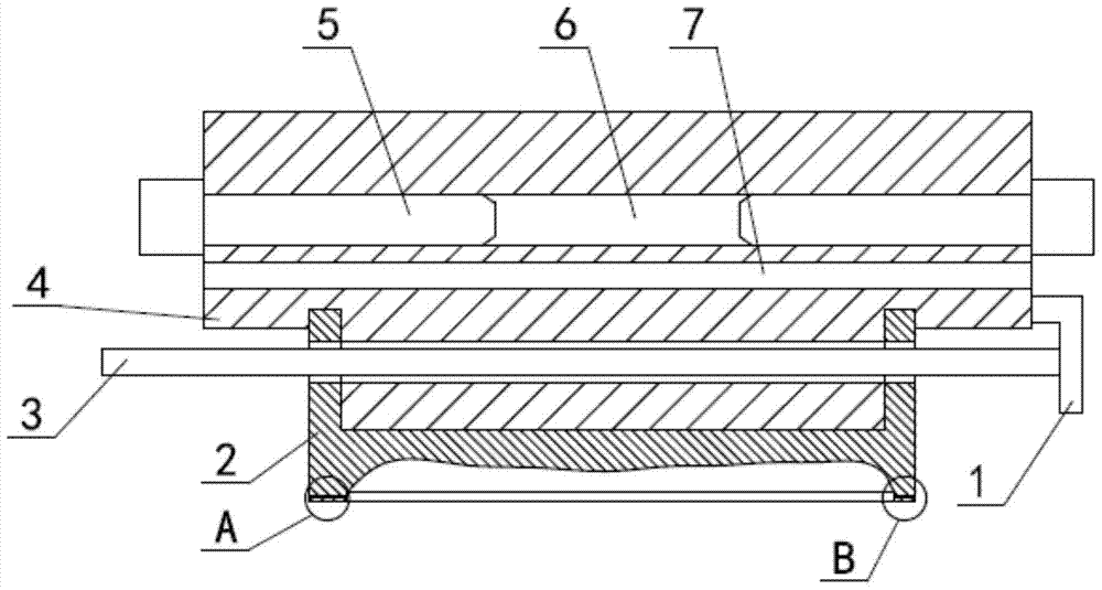
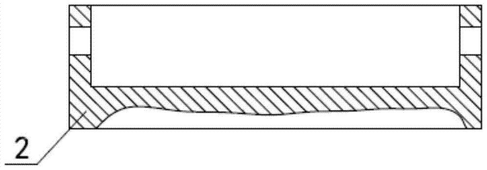
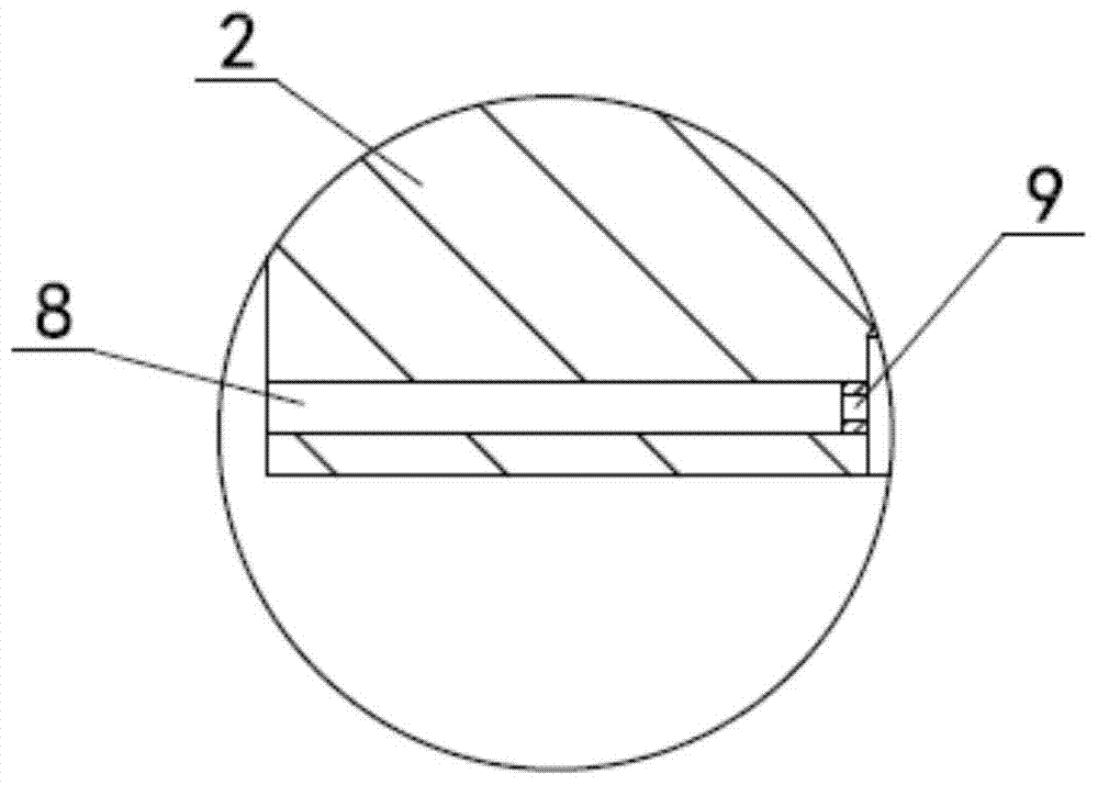
[0019] Such as figure 1 , figure 2 , image 3 , Figure 4 As shown, the electric heating rod type belt cooling upper mold for CPU fan blades includes an upper mold body 2, the lower left part of the upper mold body 2 is horizontally provided with an injection molding channel 8, and the lower right part of the upper mold body 2 is horizontally provided with an exhaust Channel 10, a heating aluminum block 4 for heating the upper die body 2 is arranged on the upper part of the upper die body 2, a groove is opened downward on the upper surface of the upper die body 2, and the lower surface of the heating aluminum block 4 extends downward There is a bump matched with the groove, and a heating chamber 6 is opened horizontally in the middle of the heating aluminum block 4, and electric heating rods 5 are installed at the left and right ends of the heating chamber 6. There is a cooling water chamber 7, the left end of the cooling water chamber 7 is provided with a water inlet, the...

Embodiment 2

[0023] This embodiment is changed on the basis of Embodiment 1, and the left exposed end of the connecting rod 3 is changed to 400 mm; the diameter of the connecting rod 3 is changed to 40 mm. Others are the same as embodiment one.

Embodiment 3

[0025] This embodiment is changed on the basis of Embodiment 1, and the left exposed end of the connecting rod 3 is changed to 500 mm; the diameter of the connecting rod 3 is changed to 50 mm. Others are the same as embodiment one.


PUM


Abstract

The invention relates to an electrical heating bar type cooling injection molding upper mould for a CPU fan blade, belonging to the technical field of injection moulds. The electrical heating bar type cooling injection molding upper mould comprises an upper mould body, wherein an injection molding channel is horizontally arranged on the left lower part of the upper mould body; an exhaustion channel is horizontally arranged on the right lower part of the upper mould body; a heating aluminum block for heating the upper mould body is arranged on the upper part of the upper mould body; a groove is formed downwards in the upper surface of the upper mould body; a lug matched with the groove extends downwards from the lower surface of the heating aluminum block; a heating cavity is horizontally formed in the middle of the heating aluminum block; electrical heating bars are mounted at the left end and the right end of the heating cavity; a cooling water cavity is horizontally formed in the heating aluminum block positioned below the heating cavity; a first lug boss with an annular structure is arranged on the side wall inside the injection molding channel; a second lug boss with an annular structure is arranged on the side wall inside the exhaustion channel. The electrical heating bar type cooling injection molding upper mould is high in heat speed, high in production efficiency and convenient to mount; moreover, the pass percentage of the product is guaranteed.

Description

technical field [0001] The invention relates to an electric heating rod type belt cooling injection molding upper mold used for CPU fan blades, and belongs to the technical field of injection molds. Background technique [0002] At present, in the production of fan blades such as CPUs, the injection molding method is commonly used, and the production efficiency is fast. If the molds usually used are in mass production, their structures are more complicated. When the structure is more complicated, it will bring many problems in the design, such as : 1. The uniformity of heating; 2. The distribution of vent holes; 3. The distribution of feed ports. If the above problems are not handled properly, the qualified rate of the product will be reduced. Contents of the invention [0003] In view of the above problems, the present invention provides an electric heating rod type cooling injection molding upper mold for CPU fan blades, which has simple structure, convenient operation, ...

Claims


Application Information

Patent Timeline
Patent Type & Authority Patents(China)
IPC IPC(8): B29C45/73B29C45/26B29L31/08
CPCB29C45/26B29C45/345B29C45/73B29L2031/08
Inventor 刘绍明
Owner ANHUI ANYUAN PLASTIC
Why Eureka
Try Eureka