Novel coiling type power transmission device

A power transmission device and winding technology, applied in the direction of transportation, packaging, conveyors, etc., can solve the problems of inability to realize two-way movement, complex structure, etc., and achieve simple and practical structure, low production and use costs, and wide application range Effect

Inactive Publication Date: 2015-04-29
SINOTRUK QINGDAO HEAVY IND
View PDF9 Cites 0 Cited by
  • Summary
  • Abstract
  • Description
  • Claims
  • Application Information

AI Technical Summary

Problems solved by technology

[0002] In the prior art, for structures such as cranes, electric hoists, and hoists, steel wire ropes are used for one-way winding, and the weight of the object is used to realize the lifting of the goods. For example, a power device for fishing oil disclosed in the patent application No. The outer surface is surrounded by a steel wire rope, and the other end of the steel wire rope is connected to the oil fishing device, and the oil fishing device is driven by the electric motor to drive the oil fishing device. With this transmission structure, the steel wire rope attached to the drum can only transmit one-way tension, and cannot realize two-way movement in the horizontal direction. or implementations that require complex structures

Method used


Image

  • Novel coiling type power transmission device
  • Novel coiling type power transmission device
  • Novel coiling type power transmission device

Examples


Embodiment 1

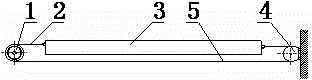
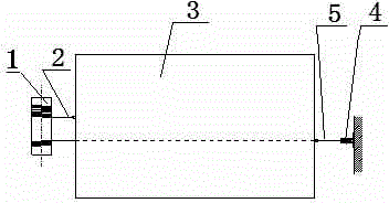
[0025] refer to figure 1 — figure 2 , the new winding type power transmission device of this embodiment, which includes a steel wire rope I2, a steel wire rope II5, a roller 1 and a reversing wheel 4, and the reversing wheel 4 is fixedly arranged at a position opposite to the roller 1, and the steel wire I2, One end of the wire rope II5 is wound on the roller 1, and the winding direction is opposite, the other free end of the wire rope I2 is directly connected to the loading platform 3, the wire rope II5 bypasses the reversing wheel 4, and then the other free end is connected to the loading platform 3.

Embodiment 2

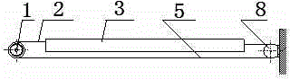
[0027] refer to image 3 — Figure 4 , the new winding type power transmission device of the present embodiment, which includes roller 1, reversing wheel I8, reversing wheel II9 and 2 groups of steel wire ropes: steel wire rope I2 and steel wire rope II5, steel wire rope III6 and steel wire rope IV7, said reversing wheel I8 , Reversing wheel II9 is ​​fixedly arranged at the position opposite to roller 1, one end of the four steel wire ropes is wound on roller 1, and the winding direction of steel wire rope I2 and steel wire rope II5 is opposite, the winding direction of steel wire rope III6 and steel wire rope IV7 is opposite, and the wire rope The winding direction of Ⅰ2 and steel wire rope Ⅲ6 is the same, and the other free ends of steel wire rope Ⅰ2 and steel wire rope Ⅲ6 are directly connected to loading platform 3, and steel wire rope Ⅱ5 and steel wire rope Ⅳ7 are respectively bypassed by reversing wheel Ⅰ8 and Ⅱ9, and then the other free end is connected to Loading plat...

Embodiment 3

[0029] The new winding type power transmission device of this embodiment includes a pulley, a belt I, a belt II, and a reversing pulley, and the reversing pulley is fixedly arranged at a position opposite to the pulley. One end is wound on the pulley, and the winding direction is opposite. The other free end of the belt I is directly connected to the loading platform, and the belt II bypasses the reversing pulley, and then the other free end is connected to the loading platform.


PUM


Abstract

The invention discloses a novel coiling type power transmission device. The device comprises a plurality of groups of conveyor belts, a conveying shaft and a turning wheel; the conveyor belts of each group are arranged in two lines and oppositely move about the conveying shaft; a conveying wheel sleeves the conveying shaft; a free end of each conveyor belt is coiled on the conveying wheel; the conveyor belts of each group are coiled in opposite directions; the other free end of each conveyor belt is connected with a moving object or a loading platform of an object to be moved; one of the conveyor belts of each group bypasses the turning wheel; when in operation, the conveying shaft drives the conveying wheel to rotate, the conveyor belts arranged in two lines oppositely move, one of the conveyor belts is coiled and tensioned and while another one of the conveyor belts is uncoiled; the conveying shaft synchronously drives, so that the conveying wheel can synchronously coil and uncoil through the conveyor belts; the conveying shaft can clockwise and anticlockwise rotate to transmit bidirectional tension force by the conveyor belts.

Description

technical field [0001] The invention belongs to the technical field of mechanical transmission devices, and in particular relates to a bidirectional mobile power transmission device. Background technique [0002] In the prior art, for structures such as cranes, electric hoists, and hoists, steel wire ropes are used for one-way winding, and the weight of the object is used to realize the lifting of the goods. For example, a power device for fishing oil disclosed in the patent application No. The outer surface is surrounded by a steel wire rope, and the other end of the steel wire rope is connected to the oil fishing device, and the oil fishing device is driven by the electric motor to drive the oil fishing device. With this transmission structure, the steel wire rope attached to the drum can only transmit one-way tension, and cannot realize two-way movement in the horizontal direction. Or the implementation requires complex structures. Contents of the invention [0003...

Claims


Application Information

Patent Timeline
Patent Type & Authority Applications(China)
IPC IPC(8): B65G17/02B65G17/34
CPCB65G17/02B65G23/24
Inventor 潘林昌秦宗江吕福麟王波马旭峰
Owner SINOTRUK QINGDAO HEAVY IND
Why Eureka
Try Eureka