A kind of residual oil hydrogenation method

The technology of residue hydrogenation and hydrogenation catalyst, which is applied in the field of residue hydrogenation, can solve the problems of complex process operation, reduced product quality, low catalyst reserve, etc., and achieves easy process operation, good product quality and high reaction efficiency. Effect

Active Publication Date: 2016-07-20
CHINA PETROLEUM & CHEM CORP +1
View PDF10 Cites 0 Cited by
  • Summary
  • Abstract
  • Description
  • Claims
  • Application Information

AI Technical Summary

Problems solved by technology

Therefore, the existing fluidized bed hydrogenation process has the following disadvantages: (1) The process operation is complicated, requiring the use of complex material level monitors and circulating oil pumps; The bottom of the reactor subsides, causing the unit to be shut down
(2) The amount of catalyst storage in the reactor is low, and the utilization rate of the reactor space is low
(3) The energy consumption is large, and the fluidization of the solid catalyst is realized by injecting a large amount of circulating oil into the circulating oil pump.
(4) There is very little hydrogen in the circulating downcomer, which is a non-hydrogen environment, and the liquid will undergo secondary cracking reactions and coking at high temperatures to reduce product quality
Due to the small difference in liquid velocity in each internal circulation zone, a large proportion of catalysts with different particle sizes will be back-mixed in each circulation zone, so it is still unavoidable to avoid the problem that catalyst deactivation is not synchronized but cannot be recovered separately

Method used


Image

  • A kind of residual oil hydrogenation method
  • A kind of residual oil hydrogenation method
  • A kind of residual oil hydrogenation method

Examples


Embodiment 1

[0093] The specific dimensions of the fluidized bed reactor used in this example are shown in Table 1 below.

[0094] Table 1

[0095] Codename

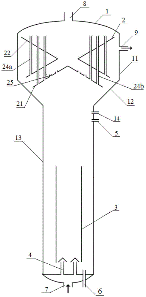
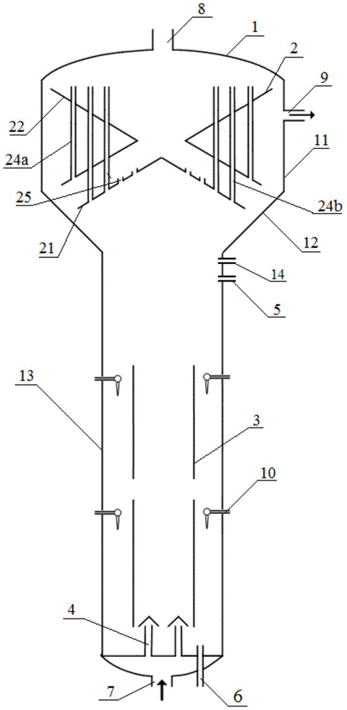
[0096] The cold model experiment was performed using the above-mentioned fluidized bed reactor, in which the solid phase catalyst added through the catalyst inlet 5 was a spherical catalyst with a particle size of 0.2-0.3 mm, and the total catalyst inventory was 60% of the effective volume of the reactor. Straight-run kerosene is used for the liquid phase, and the volumetric space velocity is 0.25-3.0h -1 . Nitrogen is used in the gas phase, and the volume ratio of gas to oil is 20-150. There are 8 gas nozzles 10, and the amount of gas injected by the gas nozzles accounts for 15% of the total gas amount. The experimental results within the range of changing conditions show that the amount of solid-phase catalyst carried is extremely low, and the maximum is 1.5 μg / g. At the same time, it can be observed in the experiment that there i...

Embodiment 2

[0098] The specific dimensions of the fluidized bed reactor used in this example are shown in Table 2 below.

[0099] Table 2

[0100] Codename

Value

Codename

Value

d 1 / mm

300

h 1 / mm

5250

d 2 / mm

220

h 2 / mm

3000

d 3 / mm

400

h 3 / mm

600

[0101] d 4 / mm

360

h 4 / mm

87

d 5 / mm

300

h 5 / mm

480

d 6 / mm

480

α / °

60

d 7 / mm

340

β / °

60

d 8 / mm

540

ω / °

60

d 9 / mm

300

φ / °

60

d 10 / mm

550

θ / °

60

d 11 / mm

440

The first gas separation pipe 24a

Total opening area / mm 2

3000

d 12 / mm

500

Second gas separation pipe 24b

Total opening area / mm 2

6000

d 13 / mm

600

The third gas separation pipe 24c

Total opening area / mm 2

8000

Total opening area of ​​through hole /

mm 2

22000

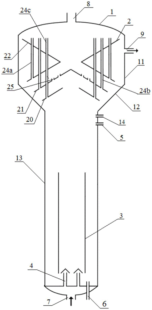
[0102] The cold model experiment was carried out with the above-mentioned fluidized bed reactor, in which the solid phase catalyst added through the catalyst inlet 5 was a spherical catalyst with a particle size of 0.5-0.6 mm, and the total catalyst storage was 50% of th...

Embodiment 3-5

[0105] Examples 3 and 4 used a medium-sized thermal reactor made according to the proportion of Example 1, and Example 5 used a medium-sized thermal reactor made according to the proportion of Example 2, in which the solid phase catalyst added through the catalyst inlet 5 was materialized The properties are shown in Table 3. The solid-phase catalyst filling amount is 55% of the effective volume of the reactor. Residual oil raw materials are shown in Table 4. The distillate oil carrying the suspended bed hydrogenation catalyst injected through the catalyst inlet 14 is shown in Table 5. The air volume injected through the nozzle 10 accounts for 20% by volume of the total air volume. The reaction conditions and test results in the reactor are shown in Table 6.

[0106] table 3

[0107]

[0108] Table 4

[0109] Nature

Value

Density (20℃) / (g / cm 3 )

1.029

Residual carbon / weight%

19.61

Sulfur content / wt%

4.53

Nitrogen content / wt%

0.23

(Ni+V) content / (μg / g)

275.8

Asphal...


PUM

PropertyMeasurementUnit
particle diameteraaaaaaaaaa
specific surface areaaaaaaaaaaa
particle diameteraaaaaaaaaa

Abstract

The invention relates to a residual oil hydrogenation method. The method is carried out in a fluidized bed reactor; the fluidized bed reactor comprises a shell (1), a three-phase separation component (2) and an inner pipe (3), wherein the shell (1) comprises an expansion section (11), a transitional section (12) and a straight cylinder section (13) in sequence from top to bottom; the diameter of the expansion section (11) is greater than that of the straight cylinder section (13); the three-phase separation component (2) is arranged in the expansion section (11) and the transitional section (12) to form a three-phase separation region; the inner pipe (3) is arranged at the lower part in the straight cylinder section (13) to form a circulation region and a fluidizing region positioned between the circulation region and the three-phase separation region. The residual oil hydrogenation method comprises the steps: injecting a fluidized bed hydrogenation catalyst and a suspended bed hydrogenation catalyst from the upper part of the fluidizing region to enable the residual oil and hydrogen to be subjected to the hydrogenation reaction in the fluidized bed reactor. According to the residual oil hydrogenation method disclosed by the invention, better reaction effect can be achieved.

Description

Technical field [0001] The invention relates to a residual oil hydrogenation method, in particular to a method for hydrotreating residual oil by adopting an inner loop fluidized bed reactor. The method is particularly suitable for processing inferior residual oil. Background technique [0002] The heavy and inferior quality of crude oil in the world is becoming more and more serious and the market demand for light oil products continues to grow. Therefore, residue hydrogenation, as an effective means of upgrading and lightening residues, has become one of the development priorities of the oil refining industry. At present, the most commonly used residual oil hydrogenation technologies in industry include fixed bed technology and fluidized bed technology. The fluidized bed hydrogenation technology has the following advantages: it can process heavy and inferior raw materials with high metal content and high carbon residue value; the reactor temperature is easy It is controlled and ...

Claims


Application Information

Patent Timeline
Patent Type & Authority Patents(China)
IPC IPC(8): C10G65/02
CPCC10G65/02C10G2300/4006C10G2300/4012C10G2300/4018C10G2300/70
Inventor 邓中活戴立顺牛传峰刘涛邵志才董凯施瑢杨清河
Owner CHINA PETROLEUM & CHEM CORP
Why Eureka
Try Eureka