
Rolling bearing device having bearing retainer and method for assemling same

A bearing cage and rolling bearing technology, applied in the directions of shafts and bearings, needle roller bearings, bearing components, etc., can solve the problems of high consumption of asymmetric bearing cages, and achieve the effect of high error rate and low cost

Inactive Publication Date: 2015-04-29
GM GLOBAL TECH OPERATIONS LLC
View PDF11 Cites 0 Cited by
  • Summary
  • Abstract
  • Description
  • Claims
  • Application Information

AI Technical Summary

Problems solved by technology

[0003] Hitherto, the assembly of asymmetrical bearing cages required high effort to check the correctness of the assembly

Method used


Image

  • Rolling bearing device having bearing retainer and method for assemling same
  • Rolling bearing device having bearing retainer and method for assemling same
  • Rolling bearing device having bearing retainer and method for assemling same

Examples


Embodiment Construction

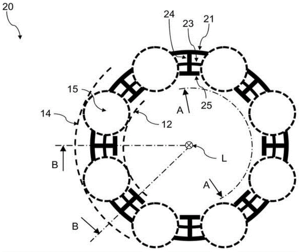
[0059] figure 1 A cross-sectional view of the bearing cage 20 of the rolling bearing device 10 according to the embodiment of the invention is shown in a radial plane with respect to the bearing axis L. As shown in FIG. exist figure 1 In this case, the rolling surfaces 12 and 14 of the rolling bearing arrangement 10 are only shown schematically with dashed lines, just like the rolling elements 15 .

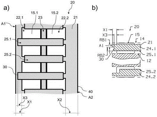
[0060] The bearing cage 20 has a radially outer peripheral wall 21 . A plurality of radial strips 24 extend radially inwards from the peripheral wall 21 , wherein the number of radial strips 24 is one less than the number of rolling elements 15 arranged on one of the two rolling element rows. In this embodiment, the rolling elements 15 are designed as cylindrical rollers.

[0061] On the radial strip 24, a rolling element row partition 23 is arranged between two rolling element rows, the rolling elements 15.1 of the first rolling element row and the rolling elements 15.2 of the...


PUM


Abstract

The present invention relates to a rolling bearing device (10) having an inner rolling surface (12) and an outer rolling surface (14); an adjustment counter backstop (35) axially fixed relative to the rolling surfaces; and a bearing retainer (20) for guiding a rolling body (15) of the rolling bearing device (10). The bearing retainer (20) can be arranged in an assembling position between the inner rolling surface (12) and the outer rolling surface (14) and in a deviation position oppositely oriented and axially shifted relative to the assembling position, and the bearing retainer (20) includes an adjustment axial backstop (30), the adjustment axial backstop (30) shapely jointed with the adjustment counter backstop (35) in the deviation position to function together.

Description

technical field [0001] The invention relates to a rolling bearing arrangement having a bearing cage with an axial adjustment stop. Furthermore, the invention relates to a motor vehicle transmission having such a rolling bearing arrangement and to a method for mounting such a rolling bearing arrangement. Background technique [0002] Especially when mounting the shaft in a motor vehicle transmission, the rolling elements of the radial rolling bearing are displaced relative to the center plane of the radially inner and outer running surfaces of the bearing, depending on the company's internal practice. Here, according to the actual operation within the enterprise, the rolling bearing device uses an asymmetrical bearing cage. [0003] Hitherto, the assembly of asymmetrical bearing cages required considerable effort for checking the correctness of the assembly. Contents of the invention [0004] The technical problem to be solved by embodiments of the invention is to provide...

Claims


Application Information

Patent Timeline
IPC IPC(8): F16C33/46F16C19/44F16C43/06
CPCF16C43/065F16C19/44F16C33/4676
Inventor M.帕洛夫
Owner GM GLOBAL TECH OPERATIONS LLC
Features
  • Generate Ideas
  • Intellectual Property
  • Life Sciences
  • Materials
  • Tech Scout
  • Unparalleled Data Quality
  • Higher Quality Content
  • 60% Fewer Hallucinations
Learn More