Integrated insulating joint

An insulating joint, integrated technology, applied in the direction of pipe/pipe joint/pipe fittings, through components, mechanical equipment, etc., can solve the problems of shortened pipeline life, long production cycle, leakage of insulating joints, etc., to improve tensile performance and The effect of bending moment resistance, improving the qualified rate of finished products, and improving sealing performance

Active Publication Date: 2015-04-29
CHENGDU SHANHAI HEAT SHRINKABLE PROD
View PDF4 Cites 2 Cited by
  • Summary
  • Abstract
  • Description
  • Claims
  • Application Information

AI Technical Summary

Problems solved by technology

[0007] In addition, according to the information collected by major domestic gas companies and customers such as PetroChina, the defects of the existing insulating joints are: (How to prevent the "gas leakage" of the insulating joints during use, because once the gas pipeline leaks, it is easy to cause a fire Accidents or pipeline explosions, major personnel or building accidents)
[0008] 1. The insulation resistance and breakdown voltage do not meet the requirements of the SY / T 0516 standard, and the cathodic protection effect cannot be achieved. The entire pipeline is severely corroded, which shortens the life of the pipeline;
[0009] 2. The insulated joints have passed the test at the customer's place, but after being installed and used for a period of time, due to the change of the buried soil and the load on the soil, the insulated joints are subject to bending stress and tensile stress due to changes in external loads, forcing the insulated joints to There is a gap between the left and right flanges and the insulating gasket in the middle or the welding quality of the welding joint causes air leakage at the insulating joint, causing the customer to have to replace the insulating joint again, and the cost loss is hundreds of thousands or millions of yuan
[0010] The above shortcomings make the product prone to air leakage, the qualified rate of finished products fluctuates greatly, the cost remains high, and the production cycle is long, which is not conducive to the market competition of the product, but also easily causes major accidents

Method used


Image

  • Integrated insulating joint
  • Integrated insulating joint

Examples


Embodiment

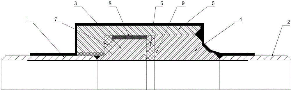
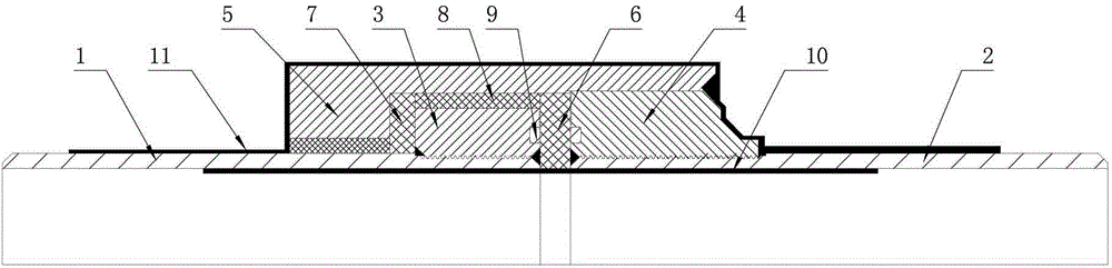
[0045] Example: such as figure 2 As shown, the integral insulating joint described in this embodiment includes a left steel short pipe 1, a right steel short pipe 2, a left flange 3, a right flange 4, a joint sleeve 5, a first insulating seal 6, a second Two insulating seals 7, insulating filling materials 8 and insulating sealing rings 9, the left short steel pipe 1 is fixedly connected to the left flange 3, the right short steel pipe 2 is fixedly connected to the right flange 4, and the The left flange 3 and the right flange 4 are fixedly connected by a first insulating seal 6 and an insulating sealing ring 9, the outer wall of the left flange 3 and the outer wall of the right flange 4 are sleeved with a joint sleeve 5, and the left Between the outer wall of the flange 3 and the joint sleeve 5 there is an insulating filler 8 and a second insulating seal 7, the outer wall of the left short steel pipe 1 has external threads, the inner wall of the left flange 3 has internal th...


PUM


Abstract

The invention relates to an integrated insulating joint. The joint comprises a left steel short pipe, a right steel short pipe, a left flange, a right flange, a joint sleeve, a first insulated sealing piece, a second insulated sealing piece, an insulated filling material and an insulated sealing ring, wherein an external thread is formed in the outer wall of the left steel short pipe; an internal thread is formed in the inner wall of the left flange; the external thread formed in the outer wall of the left steel short pipe and the internal thread formed in the inner wall of the left flange are matched to form a fixed connection mode; the threads through which the left steel short pipe and the left flange are in threaded connection are matched at the two starting ends so as to realize angle joint structure welding; an external thread is formed in the outer wall of the right steel short pipe; an internal thread is formed in the inner wall of the right flange; the external thread formed in the outer wall of the right steel short pipe and the internal thread formed in the inner wall of the right flange are matched to form a fixed connection mode; and the threads through which the right steel short pipe and the right flange are in threaded connection are matched at the two starting ends so as to realize angle joint structure welding. The yield of the finished product is high, the production cost can be greatly reduced, the production period is shortened, the joint is safe, and the standard specification is met.

Description

technical field [0001] The invention relates to an insulating joint used in a gas pressure pipeline, in particular to an integral insulating joint. Background technique [0002] Since 2008-06-16 SY / T0516-2008 "Specification Standard for Insulating Joints and Insulating Flanges" was released, all manufacturers in the country have produced various types of Integral insulated joints. [0003] Due to the basic structure of the integral insulating joint required in this standard specification, the left and right flanges and the left and right short pipes are welded, (see figure 1 ) Its main defects are: [0004] 1. Since the left and right flanges and the left and right short pipes are connected by ordinary welding, air tightness test, hydraulic test and non-destructive flaw detection must be carried out in the production process to ensure the sealing performance of the welded parts, otherwise , It is easy to cause pipeline gas leakage accidents, casualties, major explosion a...

Claims


Application Information

Patent Timeline
IPC IPC(8): F16L25/03
CPCF16L25/026F16L25/03
Inventor 张成宪邓文松袁宗明黄谋刚郑军
Owner CHENGDU SHANHAI HEAT SHRINKABLE PROD
Why Eureka
Try Eureka