Branch joint

A technology of branch joints and main pipes, which is applied in the direction of pipes/pipe joints/fittings, branch pipelines, pipes, etc., and can solve the problems of branch joint fixation and poor waterproof performance

Active Publication Date: 2015-04-29
MAEZAWA KASEI IND
View PDF9 Cites 3 Cited by
  • Summary
  • Abstract
  • Description
  • Claims
  • Application Information

AI Technical Summary

Problems solved by technology

If the hole cannot be formed by punching with good dimensional accuracy, the fixity and waterproofness of the branch joint will deteriorate

Method used


Image

  • Branch joint
  • Branch joint
  • Branch joint

Examples


no. 1 approach

[0036] Hereinafter, a first embodiment which is an example of an embodiment to which the present invention is applied (hereinafter referred to as the present embodiment) will be described in detail using the drawings. In addition, the technical scope of this invention is not limited to this embodiment. Various changes can be made to this embodiment within the range which does not deviate from the summary of this invention.

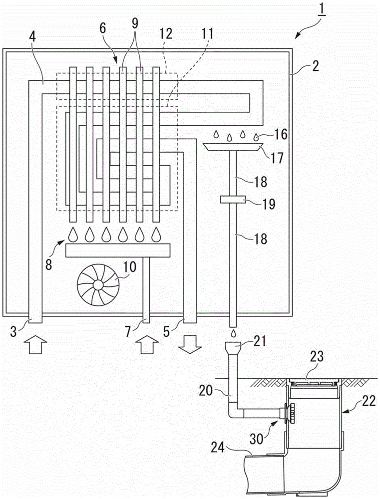
[0037] figure 1 It is a schematic diagram of applying the branch joint 30 of the first embodiment to the latent heat recovery type gas water heater 1 . figure 1 The shown latent heat recovery type gas water heater 1 is a water heater that improves the thermal efficiency of hot water by recovering the latent heat of combustion gas. The latent heat recovery type gas water heater 1 can improve the thermal efficiency of hot water of conventional water heaters by about 80% to about 95%. As a result, energy saving can be achieved, and operating costs can be g...

no. 2 approach

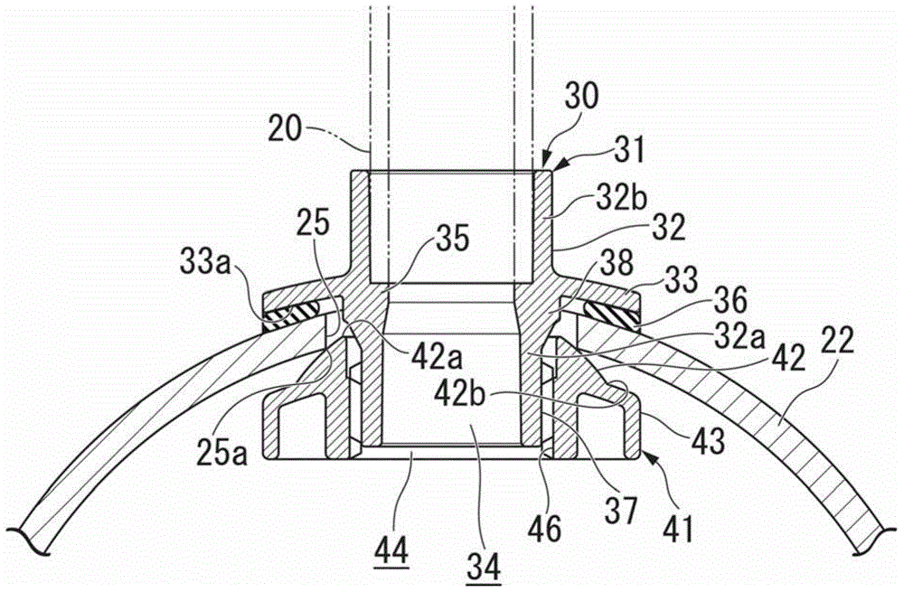
[0125] Next, use Figure 12 The branch joint 60 of the second embodiment will be described. In the second embodiment, the main body 31 of the branch joint 30 of the first embodiment is changed to a main body 61 (branch joint main body), and the fixing member 41 is changed to a fixing member 71 . The other structures that are the same as those in the first embodiment are assigned the same reference numerals, and description thereof will be omitted.

[0126] The branch joint 60 of the second embodiment is the same as the branch joint 30 of the first embodiment (refer to figure 2 ) In comparison, the engagement structure for fixing the main body 61 and the fixing member 71 is different. That is, the branch joint 60 of the second embodiment uses the internal thread as the locking portion 67 of the main body 61 and the external thread as the engaging portion 76 of the fixing member 71, and by screwing them, the branch joint 60 is fixed on the main pipe 22 .

[0127] The main b...


PUM


Abstract

The invention provides a branch joint. The branch joint is installed in a through hole in a main pipe and is connected to an auxiliary pipe to form a branch route. The branch joint has a branch joint body which is connected to an auxiliary pipe. The branch joint body comprises a cylindrical part which is inserted into the through hole of the main pipe from outside, an edge part, which is arranged on the periphery of the cylindrical part; and a fixing member, which has an inclined part that abuts the edge of the through hole from the inner side of the main pipe. The fixing member is connected to the cylindrical part of the branch joint body through threads and holds the main pipe through the inclined part and the edge part of the branch joint body.

Description

technical field [0001] The invention relates to a branch joint connecting a main pipe and a secondary pipe. Background technique [0002] In the case of connecting the main pipe and the auxiliary pipe, branch joints are generally used. For example, an opening is provided through the main pipe, and a branch joint is installed in this opening. Connect the subpipe through which the discharge water flows to the main pipe through the branch joint, or connect the subpipe through which the discharge water from the main pipe flows to the main pipe. [0003] For example, Patent Document 1 discloses a technique of connecting the main pipe and the secondary pipe by providing a hole through the main pipe using a tool such as a hole saw, and fixing a branch joint in the opening. In addition, Patent Document 2 discloses a technique in which an opening to be connected to a branch joint is inserted through a main pipe (connected pipe) using a hole opener or the like, and the branch joint ...

Claims


Application Information

Patent Timeline
Patent Type & Authority Applications(China)
IPC IPC(8): F16L41/14
CPCF16L41/14
Inventor 根本隆之下条隆史
Owner MAEZAWA KASEI IND
Why Eureka
Try Eureka