Air flue structure and air conditioner

An air duct and cavity technology, applied in the field of air conditioning, can solve the problems of reducing fluid outlet velocity and flow, noise and energy loss, and achieve the effect of improving speed and flow, reducing noise and energy loss

Active Publication Date: 2015-04-29
GREE ELECTRIC APPLIANCES INC
View PDF8 Cites 2 Cited by
  • Summary
  • Abstract
  • Description
  • Claims
  • Application Information

AI Technical Summary

Problems solved by technology

[0003] The embodiment of the present invention provides an air duct structure and an air conditioner, which can solve the problem that the flow of the fluid in the cavity of the air duct structure in the prior art has a right-angle dead angle area, which will cause certain noise and energy loss, reduce the fluid outlet velocity and flow problem

Method used


Image

  • Air flue structure and air conditioner
  • Air flue structure and air conditioner
  • Air flue structure and air conditioner

Examples


Embodiment Construction

[0021] The present invention will be described in further detail below in conjunction with the accompanying drawings and specific embodiments, but not as a limitation of the present invention.

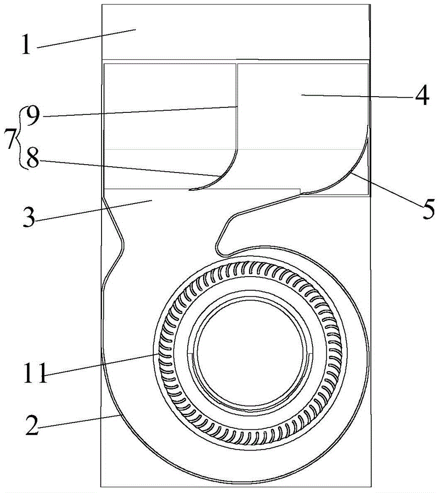
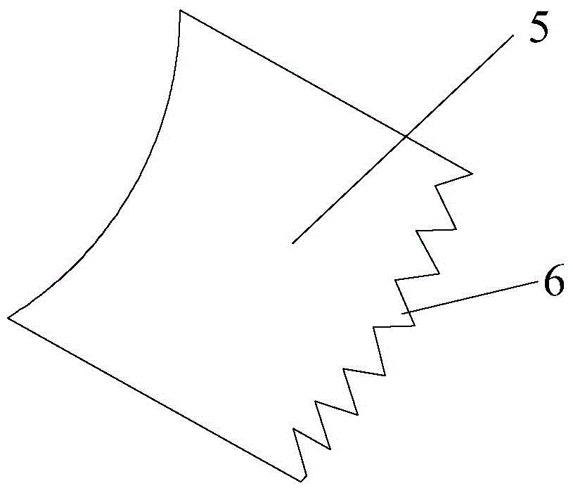
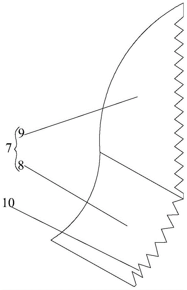
[0022] see Figure 1 to Figure 4 As shown, according to the embodiment of the present invention, the air duct structure includes a casing 1 and a volute 2 disposed in the casing 1, the volute 2 has a volute outlet 3, and the casing 1 also includes a hollow chamber communicated with the volute outlet 3 4. A first deflector 5 is arranged in the hollow chamber 4, the first end of the first deflector 5 is connected to the side wall of the volute outlet 3, and the second end of the first deflector 5 is connected to the cavity. on the side wall of chamber 4. The first deflector 5 is arranged between the volute outlet 3 at the position of the right-angle dead-angle area of ​​the cavity 4 and the sidewall of the cavity 4, and can isolate the right-angle dead-angle area from other spaces of th...


PUM


Abstract

The invention discloses an air flue structure and an air conditioner. The air flue structure comprises a shell (1) and a spiral casing (2) arranged in the shell (1), wherein the spiral casing (2) is provided with a spiral casing outlet (3); the shell (1) also comprises a hollow chamber (4) which is communicated with the spiral casing outlet (3); a first guide plate (5) is arranged in the hollow chamber (4); a first end of the first guide plate (5) is connected to the side wall of the spiral casing outlet (3); a second end of the first guide plate (5) is connected to the side wall of the hollow chamber (4). According to the air flue structure disclosed by the invention, the problem of the prior art that the fluid outlet speed and the fluid flow are reduced due to certain noise and energy loss since a right-angle dead angle zone exists when fluid flows in the hollow chamber of the air flue structure can be solved.

Description

technical field [0001] The invention relates to the technical field of air conditioning, in particular to an air duct structure and an air conditioner. Background technique [0002] In an existing centrifugal air duct, the fluid is sucked in by the centrifugal impeller from the air inlet, passes through the volute, flows out from the outlet of the volute, and directly enters the hollow chamber to flow to the outlet. Wherein, since the area of ​​the volute outlet is smaller than the hollow chamber, the airflow entering the hollow chamber at the volute outlet will cause a sharp increase in the fluid flow area, resulting in certain airflow congestion and certain noise. At the same time, the flow of fluid in the hollow chamber has a right-angle dead angle area, which will cause certain noise and energy loss, and reduce the fluid outlet velocity and flow. Contents of the invention [0003] The embodiment of the present invention provides an air duct structure and an air condit...

Claims


Application Information

Patent Timeline
Patent Type & Authority Applications(China)
IPC IPC(8): F24F13/08F24F13/24
CPCF24F13/081F24F13/24F24F2013/247
Inventor 梁浩贾铌杨勇刘伟龙柳洲
Owner GREE ELECTRIC APPLIANCES INC
Why Eureka
Try Eureka