Field calibration method and device for laser beams

An on-site calibration and laser beam technology, applied in the direction of optical devices, measuring devices, instruments, etc., can solve problems such as measurement result errors, and achieve the effect of ensuring measurement accuracy and simple and convenient calibration process

Active Publication Date: 2015-04-29
HUAZHONG UNIV OF SCI & TECH
View PDF5 Cites 22 Cited by
  • Summary
  • Abstract
  • Description
  • Claims
  • Application Information

AI Technical Summary

Problems solved by technology

[0003] For the measurement of some large free-form surface parts, such as large propeller blades, water turbine runner chambers, etc., the existing machine tool equipment is often used to detect the shape of the part with a laser displacement sensor. During the detection process, the laser The laser emitted by the displacement sensor is as coaxial as possible with the spindle axis of the machine tool, but due to installation errors or positioning errors of the machine tool itself, there will be a certain deviation between the actual direction of the laser beam and the spindle axis, and this deviation will affect the final measurement results. There is a large error, so there is an urgent need for a deviation that can accurately calibrate the direction of the laser beam to compensate for the later measurement results, so as to ensure the measurement accuracy

Method used


Image

  • Field calibration method and device for laser beams
  • Field calibration method and device for laser beams
  • Field calibration method and device for laser beams

Examples


example

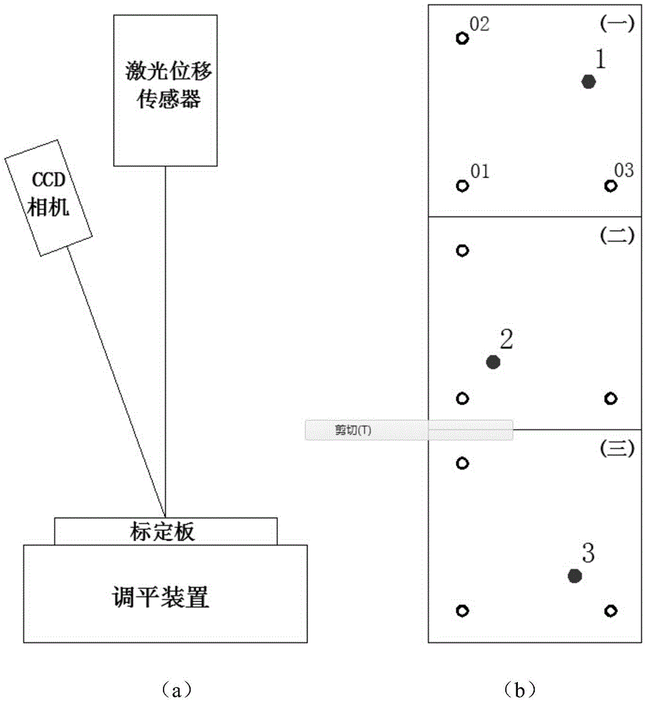
[0053] The invention is implemented on the Mikron machine tool. The sensor and CCD camera are installed as shown in the figure below. The calibration plate is placed on the machine tool workbench. The workbench itself is horizontal, and the level of the calibration plate is checked with a dial indicator before the experiment. The sensor in this experiment is installed vertically downward. The positioning accuracy of the machine tool is 2um, the CCD camera is 5 million pixels, the size of the calibration plate is 60mm*60mm, and the diameter of the through hole is 2mm. The distance D between the through holes 01 , 02 and the through holes 01 , 03 = 40 mm.

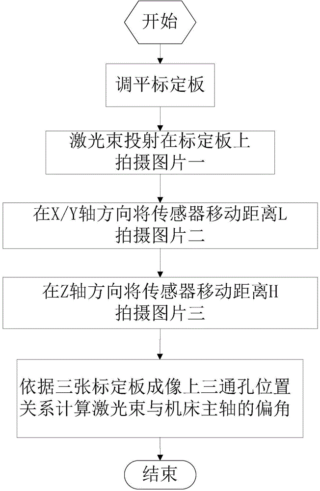
[0054] According to the calibration steps, the pictures taken in the experiment are shown in the figure below, the distance L=30mm that the machine tool moves in the X direction, and the descending distance H=50mm of the machine tool in the Z axis direction.


PUM


Abstract

The invention provides a field calibration method for laser beams. The method specifically comprises steps as follows: leveling a calibration plate, wherein the calibration plate has three through holes, and connection lines among the through holes are perpendicular; emitting a laser beam to the calibration plate to form an image by a laser displacement sensor; driving the laser displacement sensor to move for a distance in the Y-axis direction of a machine tool, and then emitting a laser beam to the calibration plate to from an image; driving the laser displacement sensor to move for a distance in the Z-axis direction of the machine tool, and then emitting a laser beam to the calibration plate to from an image; calculating deviation angles formed by the laser beams and a spindle of the machine tool according to position relations of the three through holes in the three images. The invention further provides a device for realizing the method. The device comprises the calibration plate, a leveling device, a CCD (charge coupled device) camera and a processor. According to the method and the device, the laser displacement sensor is driven by movement in all axes of the machine tool, the CCD camera is adopted to shoot images of light spots of the laser beams on the calibration plate, the direction characteristic of the laser beams is determined accurately through digital image analysis, and measurement results in the later period are compensated.

Description

technical field [0001] The invention relates to the technical field of calibrating the direction characteristic of a laser beam, and more specifically, the invention relates to a laser beam on-site calibrating method and device. Background technique [0002] As a non-contact measurement technology, laser measurement technology has greatly improved its measurement accuracy and efficiency compared with traditional non-contact probes, and is more and more widely used in the detection field. The principle of laser measurement is to use the laser displacement sensor to emit a beam of laser light on the surface of the measured object, and measure the distance from the object to the laser displacement sensor by receiving the reflected light. [0003] For the measurement of some large free-form surface parts, such as large propeller blades, turbine runner chambers and other parts, the existing machine tool equipment is often used, and then the laser displacement sensor is equipped t...

Claims


Application Information

Patent Timeline
Patent Type & Authority Applications(China)
IPC IPC(8): G01B11/02G01B11/00
Inventor 李斌熊忠星李沨郑飞刘红奇毛新勇彭芳瑜
Owner HUAZHONG UNIV OF SCI & TECH
Why Eureka
Try Eureka