
A system and method for calibrating correction factors of near-field probes using microstrip line method

A near-field probe and correction factor technology, which is applied in the direction of measuring devices, instruments, and measuring electrical variables, can solve problems such as different properties and affecting calibration accuracy

Active Publication Date: 2017-06-06
BEIJING INST OF RADIO METROLOGY & MEASUREMENT
View PDF4 Cites 0 Cited by
  • Summary
  • Abstract
  • Description
  • Claims
  • Application Information

AI Technical Summary

Problems solved by technology

[0018] For radiation diagnostic near-field probes, using the TEM chamber standard field method has the following disadvantages: a) The nature of the calibrated field of the near-field probe is different from that used; When the near-field probe is used in the near field
Therefore, different radiation methods determine different measurement signals. The calibration field is a space field, while the near-field probe measures the induced near-field emitted by the transmission signal on the microstrip line of the integrated circuit, thus affecting the accuracy of calibration.

Method used


Image

  • A system and method for calibrating correction factors of near-field probes using microstrip line method
  • A system and method for calibrating correction factors of near-field probes using microstrip line method
  • A system and method for calibrating correction factors of near-field probes using microstrip line method

Examples


Embodiment Construction

[0057] In order to illustrate the present invention more clearly, the present invention will be further described below in conjunction with preferred embodiments and accompanying drawings. Similar parts in the figures are denoted by the same reference numerals. Those skilled in the art should understand that the content specifically described below is illustrative rather than restrictive, and should not limit the protection scope of the present invention.

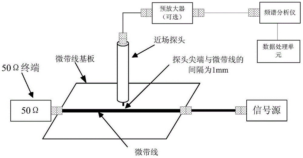
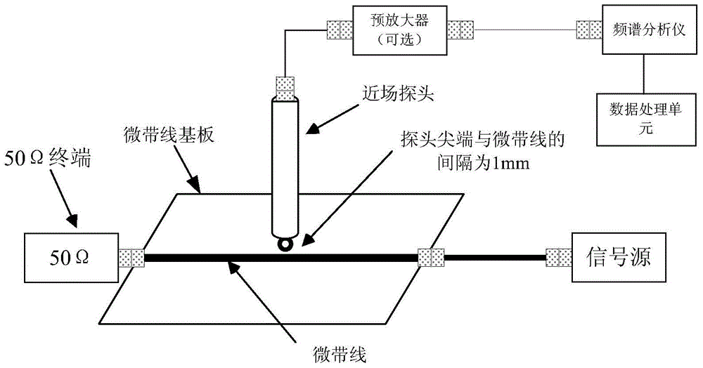
[0058] The system for calibrating the correction factor of near-field probes provided by this embodiment includes: a microstrip line placed on a microstrip line substrate, an adjustable signal source, a spectrum analyzer, a near-field probe and a 50Ω load terminal and a data processing unit connected to the spectrum analyzer;

[0059] The positional relationship between the microstrip line and the near-field probe is: place the near-field probe above the microstrip line and make the detection end of the near-field probe pe...


PUM


Abstract

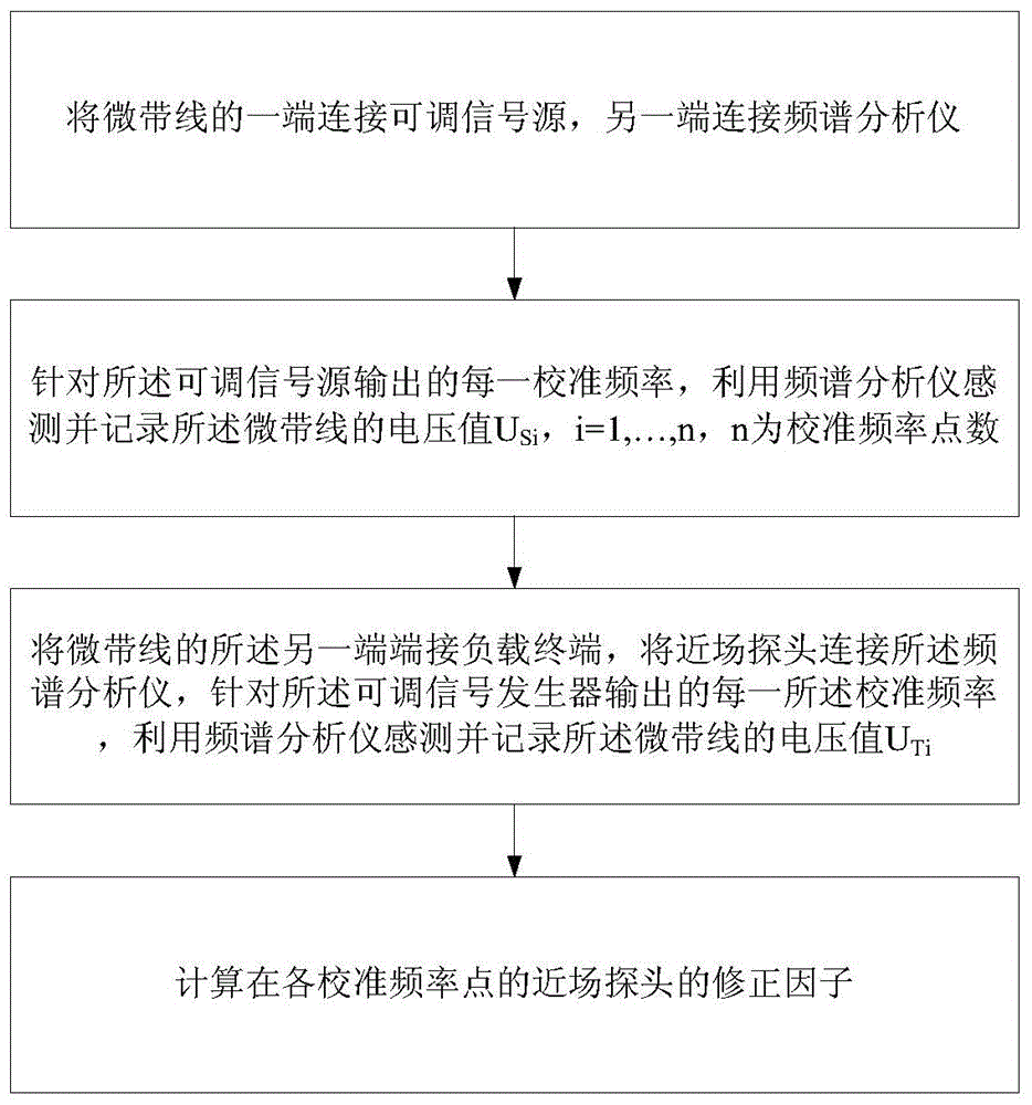
The invention discloses a system and method for correcting the correction factors of a near field probe by utilizing a microstrip line method. The system comprises a microstrip line placed on a microstrip line substrate, an adjustable signal source, a spectrum analyzer, a near field probe, a load terminal and a data processing unit connected with the spectrum analyzer, wherein the near field probe is placed above the microstrip line to be used for detecting signals sent by the adjustable signal source to the load terminal through the microstrip line; the spectrum analyzer is used for being connected with the microstrip line and used for measuring the voltage value of signals sent by the adjustable signal source to the spectrum analyzer through the microstrip line; the spectrum analyzer is also used for being connected with the near field probe to be used for measuring the voltage value of signals detected by the near field probe. The technical scheme adopted by the system disclosed by the invention lies in that a near field which is generated by the microstrip line and is close to an actual test is adopted to correct the correction factors of the near field probe under correction frequency points, and the preparation for utilizing the corrected correction factors to correct a microstrip-line radiation field in a correction test is well provided, so that the accuracy of measurement data is improved.

Description

technical field [0001] The present invention relates to near-field probe calibration. More specifically, it relates to a system and method for calibrating the correction factor of a near-field probe by using the microstrip line method. Background technique [0002] For radiation diagnostic near-field probes, the current near-field probe calibration method is to use the transverse electromagnetic wave TEM chamber standard field method for calibration. [0003] The signal source is connected to the power amplifier to inject a certain power signal into the TEM cell, and form a standard field in the TEM cell, put the near-field probe into the standard field, and calibrate the correction factor. [0004] The process of calibrating using the TEM cell standard field method is: [0005] 1) According to the requirements of the instrument manual, preheat the instrument used to stabilize the frequency and amplitude of the signal source and amplifier, complete the self-calibration of ...

Claims


Application Information

Patent Timeline
Patent Type & Authority Patents(China)
IPC IPC(8): G01R35/00
Inventor 刘星汛马蔚宇黄承祖董佳康宁余璨译彭博刘东霞闫旭红
Owner BEIJING INST OF RADIO METROLOGY & MEASUREMENT
Learn More