High-power pulse field strength calibration system and high-power pulse field strength calibration method

A technology for calibrating systems and pulse fields, applied in measuring devices, instruments, measuring electrical variables, etc., can solve problems such as inability to measure and calibrate high-power pulse field strength, and achieve the effect of meeting the needs of measurement guarantee

Pending Publication Date: 2019-01-08
BEIJING INST OF RADIO METROLOGY & MEASUREMENT
View PDF6 Cites 9 Cited by
  • Summary
  • Abstract
  • Description
  • Claims
  • Application Information

AI Technical Summary

Problems solved by technology

[0011] In order to solve one of the above-mentioned problems, this application provides a high-power pulse field strength calibration system and method to solve the problem that the high-power pulse field strength cannot be measured and calibrated

Method used


Image

  • High-power pulse field strength calibration system and high-power pulse field strength calibration method
  • High-power pulse field strength calibration system and high-power pulse field strength calibration method
  • High-power pulse field strength calibration system and high-power pulse field strength calibration method

Examples


Embodiment 1

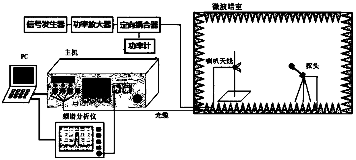
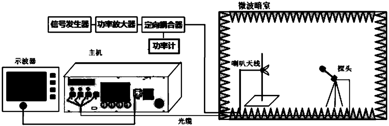
[0029] The proposal discloses a high-power pulse field strength calibration system, and the maximum amplitude that the system can calibrate can reach 3000V / m. The system includes: a horn antenna and an integrated optical electric field sensor arranged in a microwave anechoic chamber; the mouth surface of the horn antenna needs to face the integrated optical electric field sensor. The horn antenna emits a pulse field with a fixed duty ratio in the microwave anechoic chamber, and the integrated optical electric field sensor generates an induced voltage by sensing the pulse field strength. The system also includes an analysis module, which is placed outside the microwave anechoic chamber, and obtains calibration data of the pulse field strength based on the parameters of the pulse signal source and the induced voltage.

[0030] In this embodiment, the system may further include: a pulse signal source for generating a pulse field with a fixed duty ratio. The pulse signal source c...

Embodiment 2

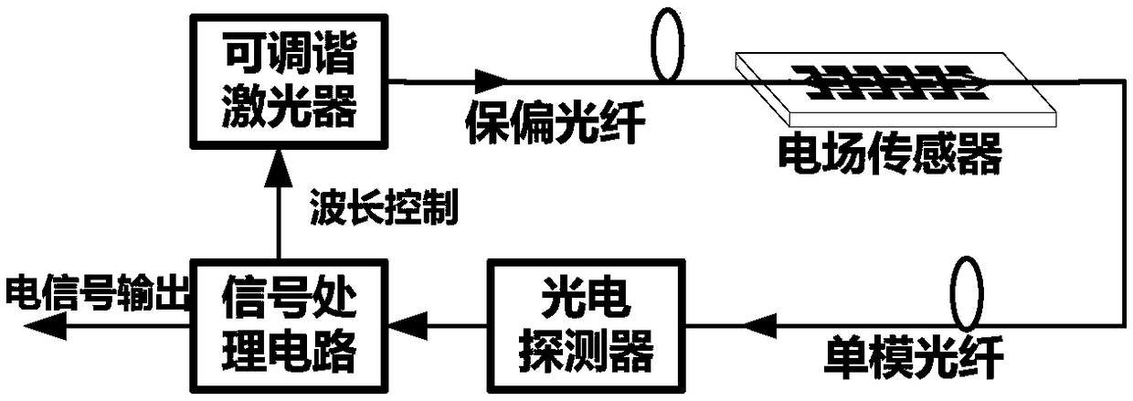
[0040] This embodiment discloses a high-power pulse field strength calibration method with a maximum amplitude of 3000V / m in the S-band (2GHz-4GHz), using an integrated optical electric field sensor (100MHz-18GHz) to calibrate the high-power pulse field strength. Among them, the integrated optical electric field sensor utilizes the electro-optic effect of the LiNbO3 crystal under the action of an external electric field to realize the measurement of the electromagnetic field. Because this kind of field sensor modulates the electrical signal onto the optical path, it is less disturbed by redundant interference objects and can be used for field strength measurement of up to tens of thousands of volts per meter. Such as image 3 As shown, the integrated optical electric field sensor includes a tunable laser, an optical fiber, an electric field sensor, a photodetector, and a signal processing circuit; the tunable laser is connected to the electric field sensor through a polarizati...


PUM


Abstract

Embodiments of the application disclose a high-power pulse field strength calibration system and a high-power pulse field strength calibration method. The system comprises: a horn antenna and an integrated optical electric field sensor disposed opposite in a microwave dark chamber, and an analysis module, wherein the horn antenna emits a pulse field with a fixed duty cycle in the microwave dark chamber, the integrated optical electric field sensor induces a pulse field strength to generate an induced voltage, and the analysis module obtains calibration data of the pulse field strength based onparameters of the pulse signal source and the induced voltage. The technical solution described in the application can accurately perform the calibration of high-power pulse field strength, and can meet the measurement guarantee requirements of high-power pulse field strength. The calibration range is up to 3000V/m, which is a significant improvement over the calibration range of the existing conventional methods (up to 1000V/m). The scheme can also calibrate time domain parameters such as pulse field strength repetition frequency, pulse width, and rise/fall time as needed.

Description

technical field [0001] The present application relates to the field of pulse strength calibration, in particular to a high-power pulse field strength calibration system and method with a maximum magnitude of 3000V / m in the S-band (2GHz-4GHz). Background technique [0002] Field strength is one of the basic parameters of radio and one of the most basic physical quantities in complex electromagnetic environments. Field sensors are commonly used equipment for measuring field strength, and the accuracy of field strength measurement results requires the guarantee of field strength sensor calibration technology. The research and construction of standard field strength environment and the calibration of field sensors have always been a development direction of domestic and foreign metrology institutions. [0003] The traditional field sensor calibration method is mainly based on the IEEE Std 1309-2013 "IEEE Standard for calibration of electromagnetic field sensors and probes, excl...

Claims


Application Information

Patent Timeline
Patent Type & Authority Applications(China)
IPC IPC(8): G01R35/00
CPCG01R35/005G01R35/007
Inventor 彭博齐万泉
Owner BEIJING INST OF RADIO METROLOGY & MEASUREMENT
Why Eureka
Try Eureka