Metal button switch and assembly

A button and metal technology, applied in the direction of electric switches, electrical components, circuits, etc., can solve the problems of numerous production processes, slow welding and wiring speed, poor replaceability, etc., to improve installation speed and detachability, improve product quality, Effect of improving self-locking performance

Active Publication Date: 2015-04-29
ZHEJIANG ZHUO LANG QI ELECTRIC CO LTD
View PDF4 Cites 11 Cited by
  • Summary
  • Abstract
  • Description
  • Claims
  • Application Information

AI Technical Summary

Problems solved by technology

[0002] The current design of similar product technology has complex structure, many parts, many production processes, high difficulty coefficient of production process, high production cost, low production efficiency, difficult to control production quality, poor self-locking stability, low waterproof performance, and difficult to effectively realize There are many defects in the function of two-color luminescence, the inability to realize the function of three-color luminescence, the slow speed of welding and wiring, and the poor interchangeability and destructiveness.

Method used


Image

  • Metal button switch and assembly
  • Metal button switch and assembly
  • Metal button switch and assembly

Examples


Embodiment 1

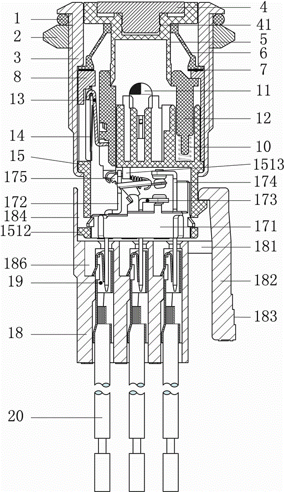
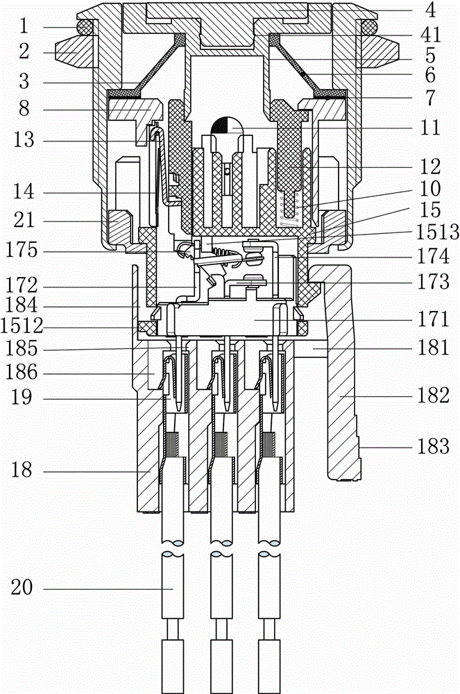
[0026] like Figures 1 to 9 As shown, the metal button switch of the present invention includes a housing 3 and a key 4 and a contact mechanism installed in the housing. The key 4 is connected in linkage with the contact mechanism 17 through a push device, and the push device and the contact mechanism A base 15 is arranged between them, two sides of the base 15 are provided with two solder pin holes 1504 for setting the solder pins 16, and a circular groove 1510 for placing the LED lamp 11 is provided at the center of the upper end of the base 15, A positioning groove 1503 for placing the resistor 9 and a square hole 1514 on the opposite side of the positioning groove 1503 are arranged on the upper end of the base 15. The contact mechanism includes a base 171, and the base 171 is inverted through the tapered bases on both sides. The hook 1713 cooperates with the barb hole 1507 provided on both sides of the lower end of the base 15, the U-shaped groove 1506 is provided at the l...

Embodiment 2

[0060] according to figure 1 , 2 . As shown in 3, the present invention is a metal button switch assembly realized according to the metal button switch described in Embodiment 1. Including the socket 18, 8 small rectangular holes are arranged inside the socket 18, the upper end of the rectangular hole is provided with a limit step of the insert spring 19, and the hanging table is arranged inside to cooperate with the V-shaped barb 191 of the insert spring 19 to be fixed in it. The upper end of the spring 19 is a rectangle compatible with the common pin 172, the normally open pin 173, and the normally closed pin 174. The S-shaped elastic sheet is arranged inside, and the A "U" shaped groove 192 is provided at the lower end to accommodate the conductor of the electric wire 20, and the B "U" The groove 193 accommodates the insulator portion of the wire 20 . A 7-shaped seesaw 182 hanging platform is arranged on one side of the outer side of the socket 18 and is interlocked with ...


PUM


Abstract

The invention discloses a metal button switch. The metal button switch is simple in structure, improves the self-locking performance and waterproof performance, achieves the double-color light emitting function more perfectly, achieves the three-color light emitting function, and improves the installation speed and dismountability. According to the technical scheme, the metal button switch comprises an outer shell, a key and a contact mechanism, wherein the key and the contact mechanism are installed in the outer shell; the key is in linkage connection with the contact mechanism through a pushing device. The metal button switch is characterized in that a base is arranged between the pushing device and the contact mechanism; two weld leg holes used for arrangement of welding legs are formed in two sides of the base; the center of the upper end of the base is provided with a round groove used for placement of an LED lamp; a positioning groove used for placement of a resistor and a square hole opposite to the positioning groove are formed in one side of the upper end of the base.

Description

technical field [0001] The invention relates to a push button switch, in particular to a metal push button switch. Background technique [0002] The current design of similar product technology has complex structure, many parts, many production processes, high difficulty coefficient of production process, high production cost, low production efficiency, difficult to control production quality, poor self-locking stability, low waterproof performance, and difficult to effectively realize There are many defects in the function of two-color light emission, the inability to realize the function of three-color light emission, the slow speed of welding connection, poor interchangeability and great destructiveness. Contents of the invention [0003] The technical problem to be solved by the present invention is to provide a device with a relatively simple structure, improved self-locking performance, improved waterproof performance, more perfect realization of the function of two...

Claims


Application Information

Patent Timeline
Patent Type & Authority Applications(China)
IPC IPC(8): H01H13/02H01H13/06H01H9/18
Inventor 柳兵
Owner ZHEJIANG ZHUO LANG QI ELECTRIC CO LTD
Why Eureka
Try Eureka