

A contactor reducing friction buffer structure
A buffer structure and contactor technology, applied in relays, electromagnetic relays, detailed information of electromagnetic relays, etc., can solve the problems of increased cost, easily damaged contact support, complex structure, etc. easily damaged effect
- Summary
- Abstract
- Description
- Claims
- Application Information
AI Technical Summary
Problems solved by technology
Method used
Image

Examples
Embodiment Construction
[0038] The present invention will be described in detail below in conjunction with the accompanying drawings and specific embodiments.
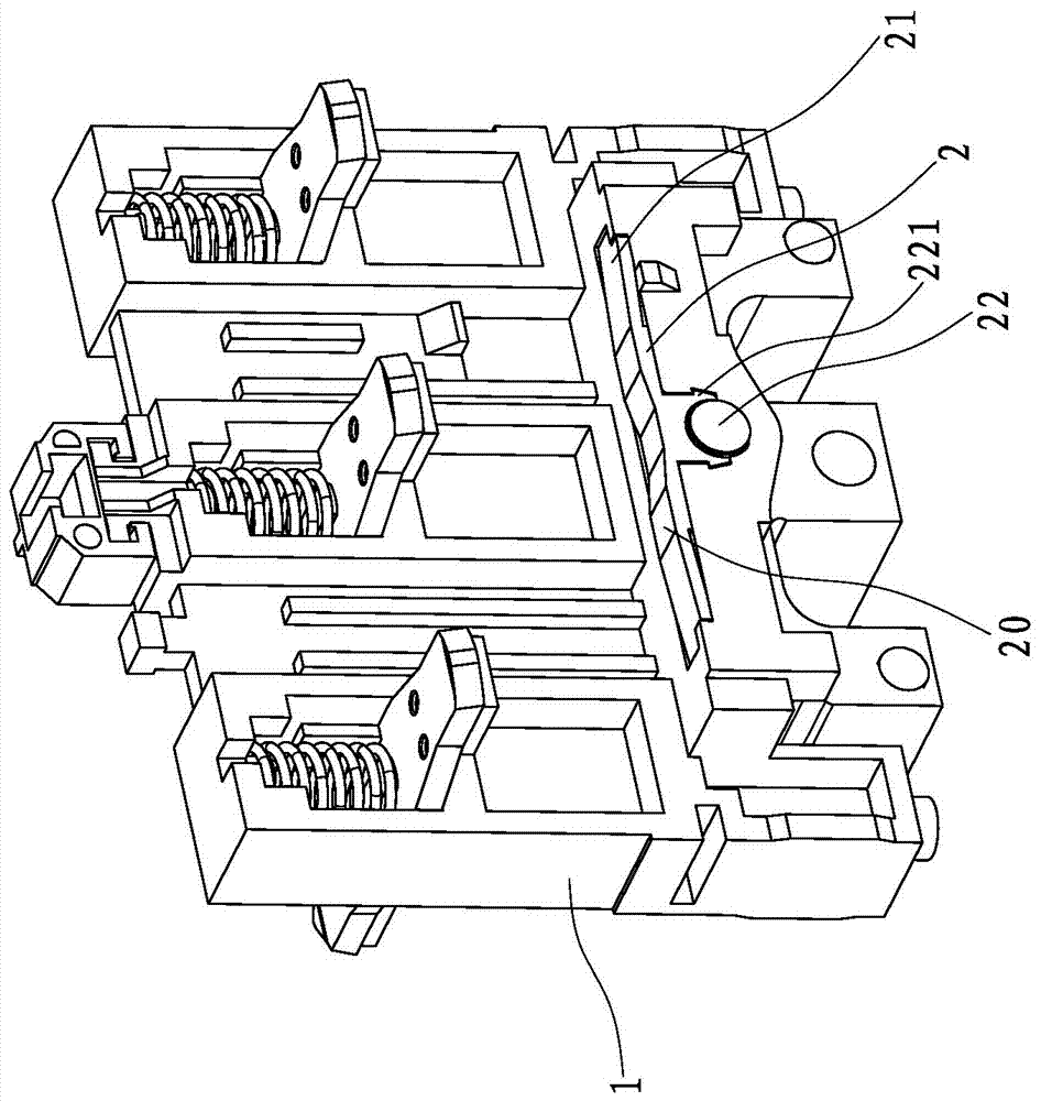
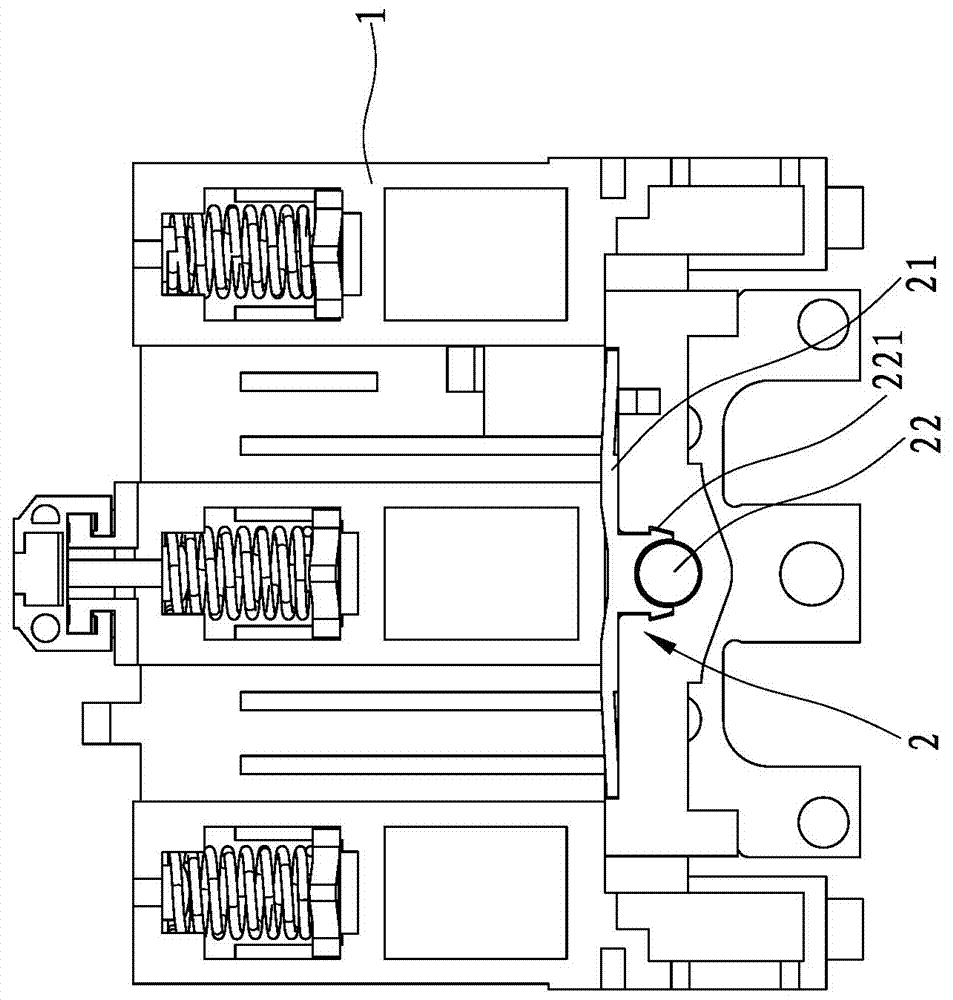
[0039] refer to Figure 1 to Figure 7 As shown, a contactor disclosed by the present invention reduces friction buffering structure, which includes a contact support 1, and a buffer member 2 is installed on the collision surface where the contact support 1 contacts the body (not shown in the figure), and the buffer member An elastic buffer surface 20 is formed on the 2, and when the contact support 1 collides with the body, due to the elastic buffer effect of the elastic buffer surface 20, the contact support 1 is less stressed and is not easily damaged, saving the cost of use.
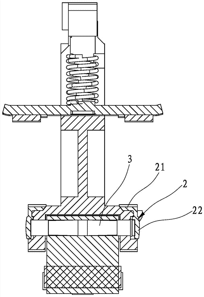
[0040] The contact support 1 installs the armature 4 through the fixed pin 3, specifically, a pin hole 11 is set on the contact support 1, such as Figure 5 As shown, the armature 4 is correspondingly provided with pin holes 41 , and then the fixing pin 3 is sequent...
PUM
 Abstract
Description
Claims
Application Information