
Input redundant circuit

A redundant circuit and input voltage technology, applied in the direction of circuit devices, emergency protection circuit devices, electrical components, etc., can solve the problems of multi-space, cost increase, occupation, etc., and achieve the goal of reducing overall cost, power loss and size Effect

Active Publication Date: 2015-04-29
ASTEC INT LTD
View PDF5 Cites 4 Cited by
  • Summary
  • Abstract
  • Description
  • Claims
  • Application Information

AI Technical Summary

Problems solved by technology

The use of two power supplies will take up more space, resulting in increased costs

Method used


Image

  • Input redundant circuit
  • Input redundant circuit
  • Input redundant circuit

Examples


Embodiment Construction

[0038] Examples of the present disclosure will now be described more fully with reference to the accompanying drawings. The following description is merely exemplary in nature and is not intended to limit the disclosure, application or uses.

[0039]Example embodiments are provided so that this disclosure will be thorough, and will fully convey the scope to those who are skilled in the art. Numerous specific details are set forth such as examples of specific components, devices and methods, to provide a thorough understanding of embodiments of the present disclosure. It will be apparent to those skilled in the art that specific details need not be employed, that example embodiments may be embodied in many different forms, and that neither should be construed to limit the scope of the disclosure. In some example embodiments, well-known processes, well-known structures, and well-known technologies are not described in detail.

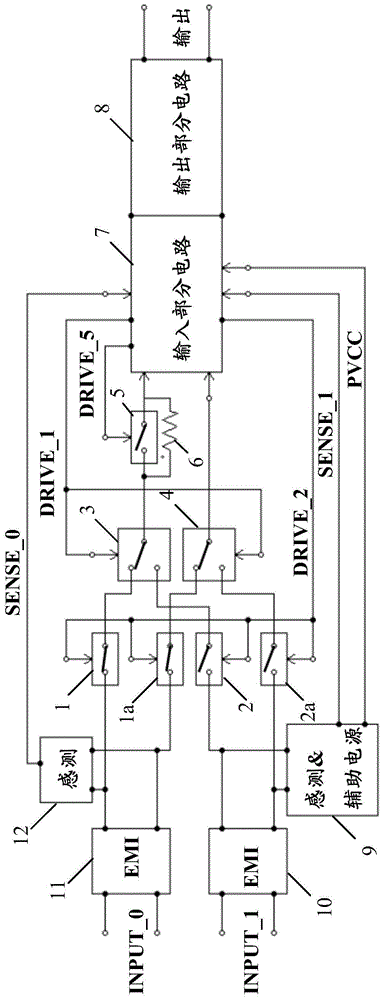
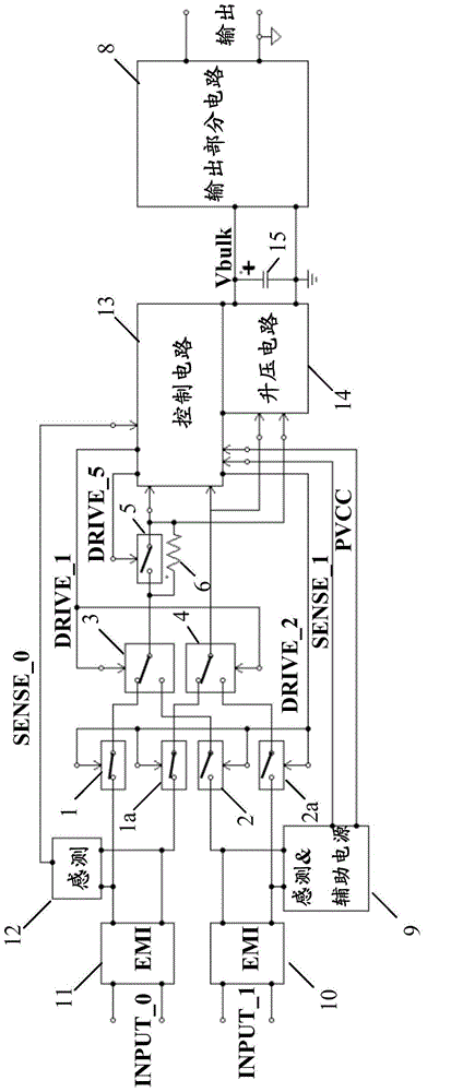
[0040] Such as figure 1 As shown, the input redu...


PUM


Abstract

An input redundant circuit according to the present disclosure may include: a core power supply unit; a first input port connected to a first input voltage; a second input port connected to a second input voltage; a relay unit connected to the first input port and the second input port to supply one of the first input voltage and the second input voltage to the core power supply unit; and a surge current limiting unit coupled to the relay unit, configured to limit a surge current generated when the relay unit is switched between the first input voltage and the second input voltage.

Description

technical field [0001] The present disclosure relates to the technical field of power supplies, in particular to an input redundancy circuit. Background technique [0002] This section provides background information related to the present disclosure which is not necessarily prior art. [0003] To have input redundancy, traditional approaches generally involve the use of two power supplies. The two power supplies run in parallel and share current at the output ports. Traditional methods generally use different input power sources, or even use battery backup power sources such as uninterruptible power supplies (UPS). The use of two power supplies will occupy more space, resulting in increased cost. Contents of the invention [0004] This section provides a general summary of the disclosure, not a comprehensive disclosure of its full scope or all of its features. [0005] It is an object of the present disclosure to provide an input redundancy circuit that enables input ...

Claims


Application Information

Patent Timeline
IPC IPC(8): H02J9/06H02H9/02
CPCH02M1/10H02M1/32H02M1/4208H02H9/025Y02B70/10H02M1/325H02H9/02
Inventor 郑锺仁
Owner ASTEC INT LTD
Learn More