
Imaging device control method and imaging device

The technology of an imaging device and a control method, which is applied in the control of the imaging device and the field of the imaging device, can solve the problems such as the lack of convenience of the shooting method, and achieve the effect of improving the convenience and convenient shooting angle

Inactive Publication Date: 2015-04-29
MEIZU TECH CO LTD
View PDF8 Cites 3 Cited by
  • Summary
  • Abstract
  • Description
  • Claims
  • Application Information

AI Technical Summary

Problems solved by technology

[0005] Based on this, it is necessary to provide a control method of an imaging device for the problem of insufficient convenience of the existing shooting method

Method used


Image

  • Imaging device control method and imaging device
  • Imaging device control method and imaging device

Examples


Embodiment Construction

[0039] In order to make the object, technical solution and advantages of the present invention clearer, the present invention will be further described in detail below in conjunction with the accompanying drawings and embodiments. It should be understood that the specific embodiments described here are only used to explain the present invention, not to limit the present invention.

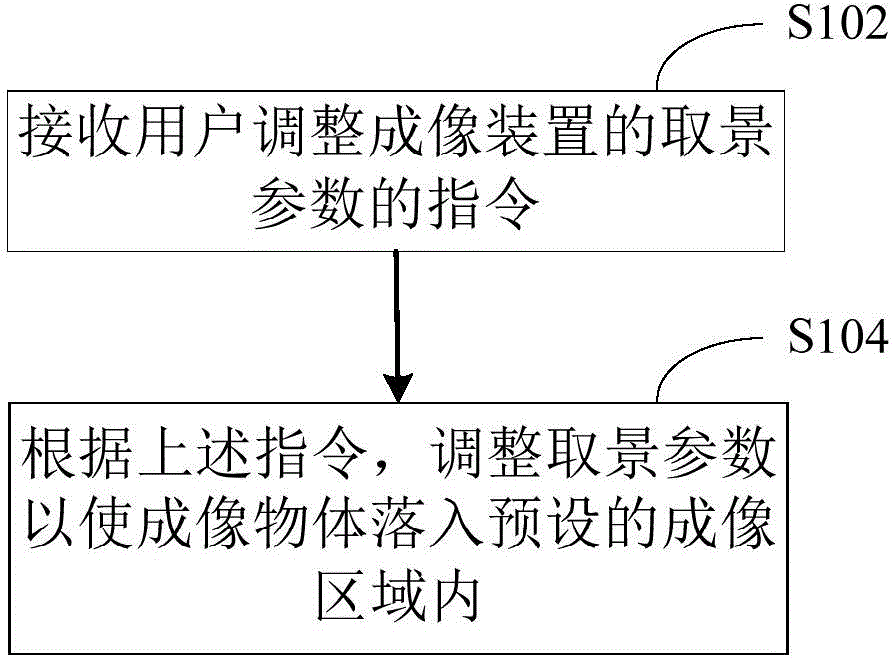
[0040] Such as figure 1 As shown, in one embodiment, a method for controlling an imaging device is provided. The method is applied to a shooting terminal as an example, and the shooting terminal includes but is not limited to various cameras equipped with cameras, smart phones, and tablet computers. , personal digital assistants, e-book readers, video players and smart terminals such as laptop computers.

[0041] The method comprises the steps of:

[0042] Step S102, receiving an instruction from a user to adjust a viewing parameter of an imaging device.

[0043] In this embodiment, the terminal...


PUM


Abstract

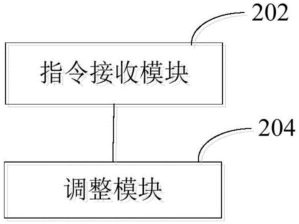
The invention provides an imaging device control method. The method comprises steps as follows: receiving an instruction of a user for adjusting view-finding parameters of an imaging device; adjusting the view-finding parameters according to the instruction so as to enable an object requiring imaging to fall into a preset imaging area. With the adoption of the method, shooting convenience can be improved. Besides, the invention further provides the imaging device.

Description

technical field [0001] The present invention relates to the technical field of mobile smart terminals, in particular to a method for controlling an imaging device and the imaging device. Background technique [0002] With the rapid development of shooting technology, there are more and more shooting methods for shooting terminals. In order to improve the user's shooting experience, shooting technology by controlling the display screen has emerged to replace the traditional button shooting technology, such as touch-screen mobile phones, users can shoot objects by touching the display screen of the mobile phone . [0003] However, the inventors have found that at least the following technical problems exist in the prior art: [0004] The existing camera is fixedly installed on the front or back of the shooting terminal. When the user takes pictures of objects in different positions, it is necessary to constantly change the shooting angle of the shooting terminal to take pict...

Claims


Application Information

Patent Timeline
IPC IPC(8): H04N5/232
Inventor 廖伟健
Owner MEIZU TECH CO LTD
Learn More