Telephone receiver provided with improved structure

A receiver, an improved technology, applied in the direction of sensors, electrical components, etc., can solve the problems that affect the vibration of the diaphragm up and down, the gap is small, and the isolation between the front and rear chambers is not complete, so as to achieve the effect of not being easy to rust and improving adaptability

Inactive Publication Date: 2015-04-29
SUZHOU YICHUAN TECH CO LTD
View PDF5 Cites 16 Cited by
  • Summary
  • Abstract
  • Description
  • Claims
  • Application Information

AI Technical Summary

Problems solved by technology

[0003] In traditional receivers, the diaphragm is generally connected to the inner wall of the housing, that is, a protrusion or boss is provided on the inner wall of the housing, and then the two ends of the diaphragm are sealed and connected to the surface of the protrusion or boss. In this connection method, it is necessary to seal the periphery of the diaphragm and the edge of the protrusion or the boss to ensure the isolation of the front cavity and the rear cavity of the receiver, but because the connection part is located on the inner wall of the shell, the gap is too small, and the It is difficult to glue, it is difficult to ensure the sealing of the joint, and in the process of sealing glue, glue leakage and overflow phenomenon are easy to occur, so the isolation between the front and rear chambers will not be complete, resulting in sound leakage; at the same time, the glue overflows When the volume of the receiver is the same, it is easy to cause it to stick to the diaphragm, which affects the up and down vibration of the diaphragm; in addition, since the connection surface of the diaphragm is located on the inner wall of the shell, in the case of the same volume of the receiver, the diaphragm is correspondingly reduced, and the sound of the receiver Loudness becomes smaller

Method used


Image

  • Telephone receiver provided with improved structure
  • Telephone receiver provided with improved structure

Examples


Embodiment Construction

[0028] The following will clearly and completely describe the technical solutions in the embodiments of the present invention with reference to the accompanying drawings in the embodiments of the present invention. Obviously, the described embodiments are only some, not all, embodiments of the present invention. Based on the embodiments of the present invention, all other embodiments obtained by persons of ordinary skill in the art without creative efforts fall within the protection scope of the present invention.

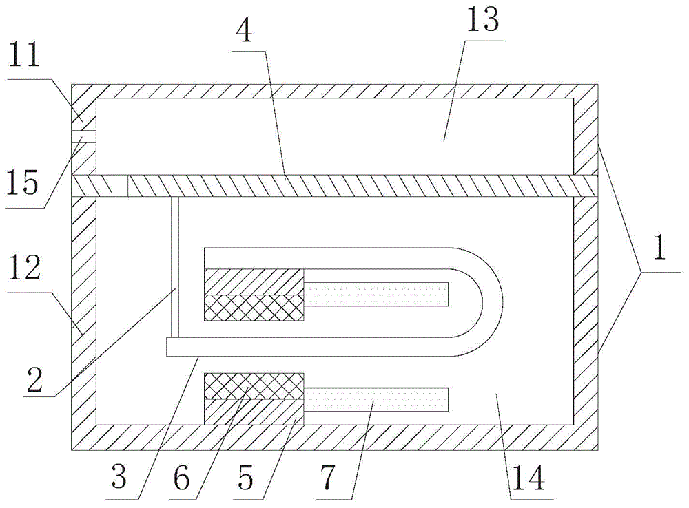
[0029] In order to achieve the purpose of the present invention, as figure 1 As shown, in some embodiments of the receiver with improved structure of the present invention, it includes a shielding shell 1 and a moving iron unit arranged in the shielding shell 1, a conductive rod 2, an armature 3 and a diaphragm 4, and the conductive rod 2 The two ends of the two are respectively connected to the armature 3 and the diaphragm 4, and the moving iron unit drives the ar...


PUM


Abstract

The invention discloses a telephone receiver provided with an improved structure. The telephone receiver comprises a shielding shell, a moving iron unit, a conduction rod, an armature and a vibrating film, wherein the moving iron unit, the conduction rod, the armature and the vibrating film are arranged in the shielding shell. The two ends of the conduction rod are connected with the armature and the vibrating film respectively, the moving iron unit drives the armature to vibrate up and down and accordingly the conduction rod is driven to drive the vibrating film to vibrate up and down; the shielding shell comprises a shell cover and a shell body in the vibration direction of the vibrating film, and the edge of the front side and the edge of the back side of the vibrating film are connected with the shell cover and the outer wall of the shell body respectively. The telephone receiver provided with the improved structure is simple in manufacturing technology, reduces production cost, and is large in sound loudness.

Description

technical field [0001] The invention relates to the field of earphone receivers, in particular to a receiver with an improved structure. Background technique [0002] The receiver, also known as the earpiece, is an electroacoustic device that converts audio electrical signals into sound signals without sound leakage. It is widely used in communication terminal equipment such as mobile phones, fixed phones, and earphones to realize audio, such as voice and music. Waiting for replay. [0003] In traditional receivers, the diaphragm is generally connected to the inner wall of the housing, that is, a protrusion or boss is provided on the inner wall of the housing, and then the two ends of the diaphragm are sealed and connected to the surface of the protrusion or boss. In this connection method, it is necessary to seal the periphery of the diaphragm and the edge of the protrusion or the boss to ensure the isolation of the front cavity and the rear cavity of the receiver, but bec...

Claims


Application Information

Patent Timeline
Patent Type & Authority Applications(China)
IPC IPC(8): H04R11/06
Inventor 周巍
Owner SUZHOU YICHUAN TECH CO LTD
Why Eureka
Try Eureka