Instant water dispenser

A water drinker, instant heating technology, applied in beverage preparation devices, household appliances, applications, etc., can solve problems such as heater damage, product inconvenience, dry burning without water, etc., and achieve the effect of improving service life and reducing maintenance costs.

Inactive Publication Date: 2015-05-06
JOYOUNG CO LTD
View PDF4 Cites 7 Cited by
  • Summary
  • Abstract
  • Description
  • Claims
  • Application Information

AI Technical Summary

Problems solved by technology

[0002] The instant water dispenser in the prior art is generally composed of main components such as a water tank, a heater, a water outlet structure, a pump and an electric control element. The water pump is connected to the water inlet of the heater. When working, the water pump sends cold water into the heater. The water flows through the flow channel in the heater to achieve rapid heating, and the boiled hot water flows out from the heater into the water outlet structure, and then flows out from the water outlet; when the heater stops heating, the residual heat of the heater continues to heat due to its thermal inertia. The water inside the heater is heated, because the flow channel area of ​​the heater is small and the heating power is high, the heated hot water is vaporized in a large amount, making the heater in an anhydrous and dry state, which can easily cause the heater to The damage caused by the product is inconvenient to use and brings users a very bad feeling

Method used


Image

  • Instant water dispenser
  • Instant water dispenser
  • Instant water dispenser

Examples


Embodiment approach 1

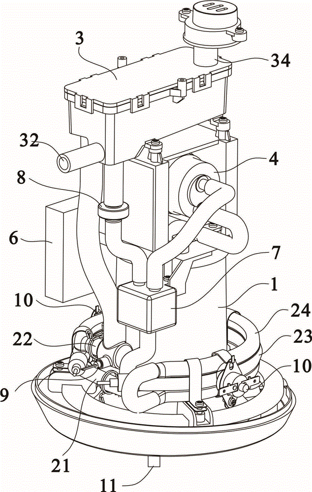
[0031] Embodiment 1: The water storage chamber and the heating device are fixedly connected together with fasteners, and the water drain hole at the bottom of the water storage chamber is attached to the water inlet end at the top of the heating device and is in airtight communication.

Embodiment approach 2

[0032] Embodiment 2: The water storage cavity and the water vapor separation box are integrally injection molded, or the water storage cavity is installed and fixed at the lower part of the water vapor separation box, and the water storage cavity is connected with the heating device through a pipe.

Embodiment approach 3

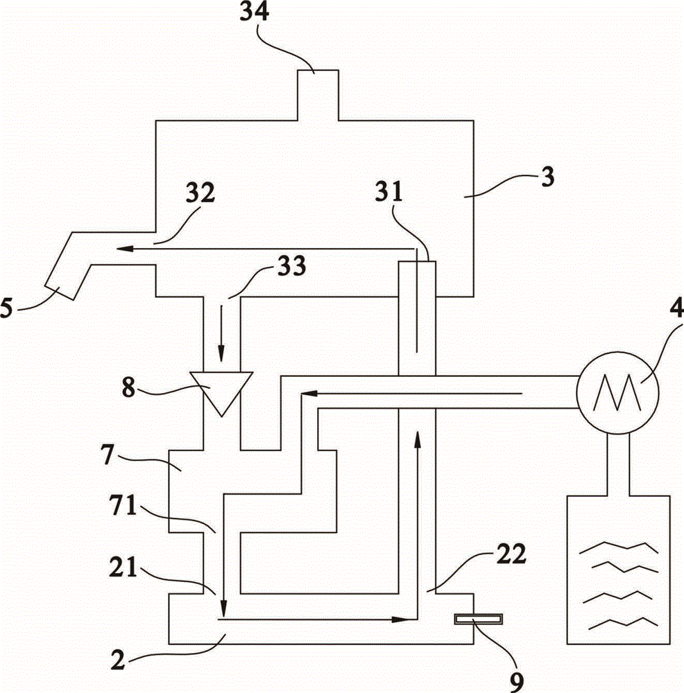
[0033] Embodiment 3, in order to make the structure of the product simpler, the water storage chamber is set as a section of pipeline that feeds water from the upper part, and the diameter of the inlet pipe of the pipeline is larger than the diameter of the outlet pipe, the water inlet pipe of this pipeline is connected with the water pump, and the pipeline The outlet pipe of the outlet pipe communicates with the water inlet end of the heating device located below it.

[0034] In the optimization scheme of this embodiment, the control valve is a one-way valve, and its working principle: when the instant water dispenser is working, the cold water is sent into the water storage chamber by the water pump through the pipeline, and a certain fluid pressure is formed in the pipeline, and the pressure in the pipeline is greater than Atmospheric pressure in the water vapor separation box, the one-way valve is closed, the cold water in the water storage chamber flows into the heating de...


PUM


Abstract

The invention relates to the technical field of kitchen appliances, in particular to an instant water dispenser. A heating device of the instant water dispenser is arranged at the lower part of a water vapor separating box; a water inlet end and a water outlet end are both communicated with the water vapor separating box; a communicating passage between the water inlet end and the water vapor separating box is provided with a control valve; the control valve controls waterflow to uniaxially flow to the water inlet end. After the heating device stops heating, water stored in the water vapor separating box can be supplemented to a space, which is lack of water due to great boiling water vaporization caused by waste heat, of the heating device by virtue of the control valve, and the heating device is cooled by the water, so that the heating device is prevented from being burnt out by high temperature, the service life of a product is prolonged, and the maintenance cost is lowered.

Description

technical field [0001] The invention relates to the technical field of kitchen appliances, in particular to an instant drinking water dispenser. Background technique [0002] The instant water dispenser in the prior art is generally composed of main components such as a water tank, a heater, a water outlet structure, a pump and an electric control element. The water pump is connected to the water inlet of the heater. When working, the water pump sends cold water into the heater. The water flows through the flow channel in the heater to achieve rapid heating, and the boiled hot water flows out from the heater into the water outlet structure, and then flows out from the water outlet; when the heater stops heating, the residual heat of the heater continues to heat due to its thermal inertia. The water inside the heater is heated, because the flow channel area of ​​the heater is small and the heating power is high, the heated hot water is vaporized in a large amount, making the ...

Claims


Application Information

Patent Timeline
Patent Type & Authority Applications(China)
IPC IPC(8): A47J31/00A47J31/46
Inventor 朱泽春李军刘峻廷杨劲丰
Owner JOYOUNG CO LTD
Why Eureka
Try Eureka