Broadband high-voltage narrow pulse system with adjustable pulse width and amplitude and pulse generation method

A technology of narrow pulse and pulse amplitude, which is applied in the field of high-frequency and high-voltage pulses, can solve the problems of low pulse frequency, excitation signal bandwidth, difficult amplitude adjustment and control, etc., and achieve the effect of increasing switching speed

Active Publication Date: 2017-01-18
SUZHOU INST OF BIOMEDICAL ENG & TECH CHINESE ACADEMY OF SCI
View PDF5 Cites 0 Cited by
  • Summary
  • Abstract
  • Description
  • Claims
  • Application Information

AI Technical Summary

Problems solved by technology

[0003]Technical problem to be solved: In the conventional ultrasound imaging system, the bandwidth and amplitude of the excitation signal are not easy to adjust and control, and the pulse frequency is low, which cannot be compared Good to meet the needs of the use of ultrasound imaging systems

Method used


Image

  • Broadband high-voltage narrow pulse system with adjustable pulse width and amplitude and pulse generation method
  • Broadband high-voltage narrow pulse system with adjustable pulse width and amplitude and pulse generation method
  • Broadband high-voltage narrow pulse system with adjustable pulse width and amplitude and pulse generation method

Examples


Embodiment 1

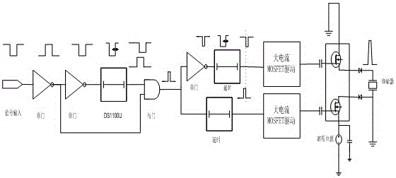
[0046]Field editable gate array output control signal (logic level is LVPECL), connected to SN65LVELT23DGK to convert LVPECL level to LVTTL level, the signal is divided into two channels, one and the other pass through the inverter SN74LVC1G04, and then connect to the delay device DS1100U- 35+ delay 7ns and then connect with another channel to the input terminal of AND gate SN74AHCT1G08, and the output signal of AND gate is divided into two channels, one channel is connected to P-type MOSFET drive device EL7158 after DS1100U delay, and the other channel is connected to DS1100U delay and then connected to N Type MOSFET drive device EL7158, two pieces of EL7158 respectively control the P-type MOSFET and N-type MOSFET to turn on and off, the high-voltage power supply EMCO-CA02P output terminal (pin 1) is connected to the P-type MOSFET source output control terminal (pin 2) to the digital-to-analog converter The output, the input terminal of the digital-to-analog converter is conne...

Embodiment 2

[0048] The pulse signal output by the AC signal source Agilent 81150A is used as the input signal, the pulse frequency is 1KHz, the amplitude is 4V, the pulse rise time is 10ns, the fall time is 10ns, and the pulse width is 100ns. The signal is divided into two channels, one channel is inverted by the NOT gate SN74LVC1G04, and then delayed by the delay device DS1100U, and then connected to the input terminal of the AND gate SN74AHCT1G08 with the other input signal, and the output signal of the AND gate is divided into two channels, one channel is delayed by the DS1100U Control the P-type MOSFET to drive the EL7158, so that another DS1100U controls the N-type MOSFET to drive the EL7158 after a delay, and the two EL7158 control the P-type MOSFET and the N-type MOSFET to turn on and off, and the high-voltage power supply EMCO-CA02P output terminal (pin 1) is connected to the P-type The MOSFET source, the output control terminal (pin 2) is connected to the output terminal of the di...


PUM


Abstract

The invention belongs to the technical field of high-frequency and high-voltage pulses, and discloses a broadband high-voltage narrow pulse system and a pulse generation method with adjustable pulse width and amplitude. The system includes a control signal adjustment module, a MOSFET drive module, a P-type MOSFET and an N-type MOSFET, and a pulse width The value adjustment module, the control signal adjustment module is connected to the MOSFET drive module, the MOSFET drive module is connected to the P-type MOSFET and the N-type MOSFET, and the pulse amplitude adjustment module is connected to the P-type MOSFET and the N-type MOSFET. The pulse width and amplitude generated by the broadband high-voltage narrow pulse system with adjustable pulse width and amplitude of the present invention are easy to adjust and control, and the pulse frequency is very high, which can be used to improve the corresponding performance of the high-frequency ultrasonic imaging system, and can also meet Transducer testing and imaging applications at different frequencies.

Description

technical field [0001] The invention belongs to the technical field of high-frequency and high-voltage pulses, and relates to a high-frequency and high-voltage pulse system and a pulse generation method, in particular to a broadband high-voltage narrow pulse system and a pulse generation method with adjustable pulse width and amplitude. Background technique [0002] The high-voltage pulse excitation module is a key component in ultrasonic equipment. In the ultrasonic imaging system, the transducer is excited by high-voltage pulses to generate ultrasonic waves, and then the transducer receives tissue reflection echo signals for imaging. The high-voltage pulse transmission module is an important part of the pulse-echo ultrasonic diagnostic equipment, which has a great influence on the imaging and signal-to-noise ratio of the instrument. The current ultrasonic transducer equipment generally works below 20MHz, and the corresponding excitation pulse frequency is easy to achieve....

Claims


Application Information

Patent Timeline
Patent Type & Authority Patents(China)
IPC IPC(8): A61B8/12A61B8/10
CPCA61B8/10A61B8/12A61B8/14A61B8/4411
Inventor 吕铁军向永嘉徐杰崔崤峣
Owner SUZHOU INST OF BIOMEDICAL ENG & TECH CHINESE ACADEMY OF SCI
Why Eureka
Try Eureka